Automatic Fan Speed Controller (Temperature-Based)
# 🔥 Automatic Fan Speed Controller (Temperature-Based) ## 📌 Project Overview The Automatic Fan Speed Controller is a smart automation system that automatically controls the speed of a DC fan based on temperature. The system uses: - Arduino Uno - DHT11 temperature sensor - MOSFET - DC fan When temperature increases, the fan speed increases automatically. --- # 🛠️ Components Used | Component | Function | |---|---| | Arduino Uno | Main controller | | DHT11 Sensor | Reads temperature | | DC Fan | Cooling device | | MOSFET (IRLZ44N) | Controls fan speed | | 10kΩ Resistor | Pull-up resistor | | 220Ω Resistor | Protects MOSFET | | 1N4007 Diode | Prevents voltage spikes | | Power Supply | Powers the fan | | Jumper Wires | Connections | --- # 🔌 Pin Connections ## 🌡️ DHT11 Sensor | DHT11 Pin | Arduino | |---|---| | VCC | 5V | | DATA | D2 | | GND | GND | ### Additional Connection - 10kΩ resistor between VCC and DATA --- ## ⚡ MOSFET Connections ### MOSFET Pin Arrangement ```text Flat side facing you: LEFT = Gate (G) MIDDLE = Drain (D) RIGHT = Source (S) ``` | MOSFET Pin | Connection | |---|---| | Gate | Arduino D9 through 220Ω resistor | | Drain | Fan negative (-) | | Source | GND | --- # 🌀 Fan Connection | Fan Wire | Connection | |---|---| | Positive (+) | External Power Supply + | | Negative (-) | MOSFET Drain | --- # ⚠️ Diode Connection | Diode Side | Connection | |---|---| | Stripe Side | Fan Positive (+) | | Other Side | Fan Negative (-) | --- # 🧠 Working Principle 1. DHT11 reads temperature. 2. Arduino processes the temperature value. 3. Arduino sends PWM signal to MOSFET. 4. MOSFET controls fan speed. 5. Higher temperature → higher fan speed. 6. Lower temperature → lower fan speed. --- # 🚨 Problems Faced | Problem | Solution | |---|---| | Error reading temperature | Corrected wiring and added resistor | | Fan not spinning | Fixed MOSFET connection | | Fan always full speed | Corrected PWM code | --- # 💻 Arduino Code ```cpp analogWrite(FAN_PIN, fanSpeed); ``` --- # 🌍 Applications - Smart home cooling - Computer cooling systems - Industrial automation - Greenhouse temperature control --- # ✅ Conclusion The Automatic Fan Speed Controller is an intelligent embedded system that improves cooling efficiency and automates temperature control using Arduino and sensors.

 Robotics
53
Robotics
53
MediBot: A Continuous AI Patient Monitoring System for Nigerian Hospitals
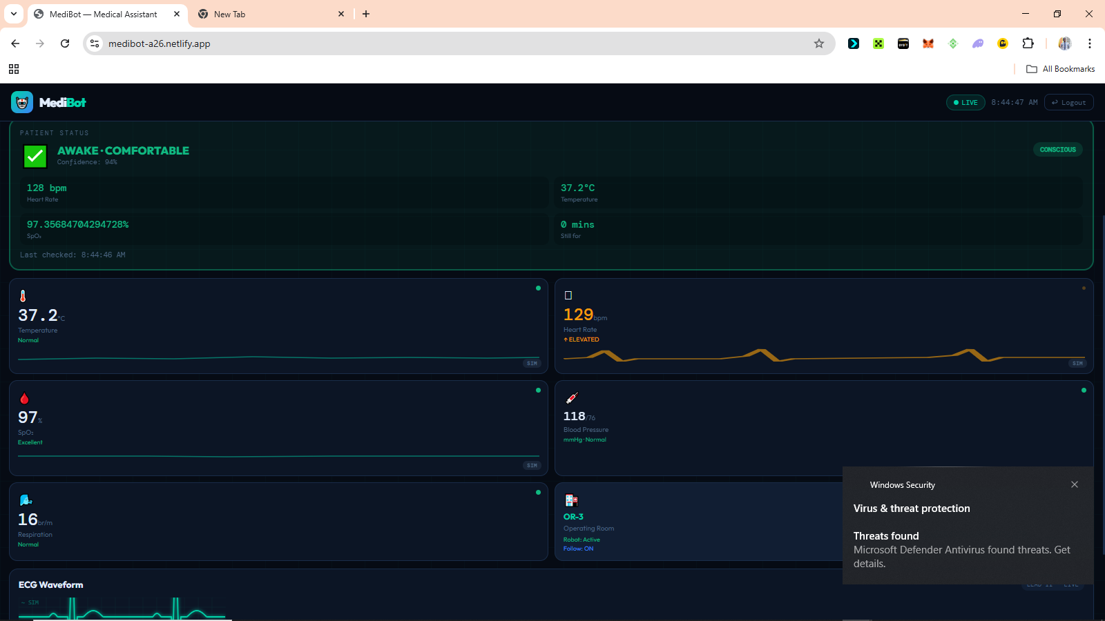
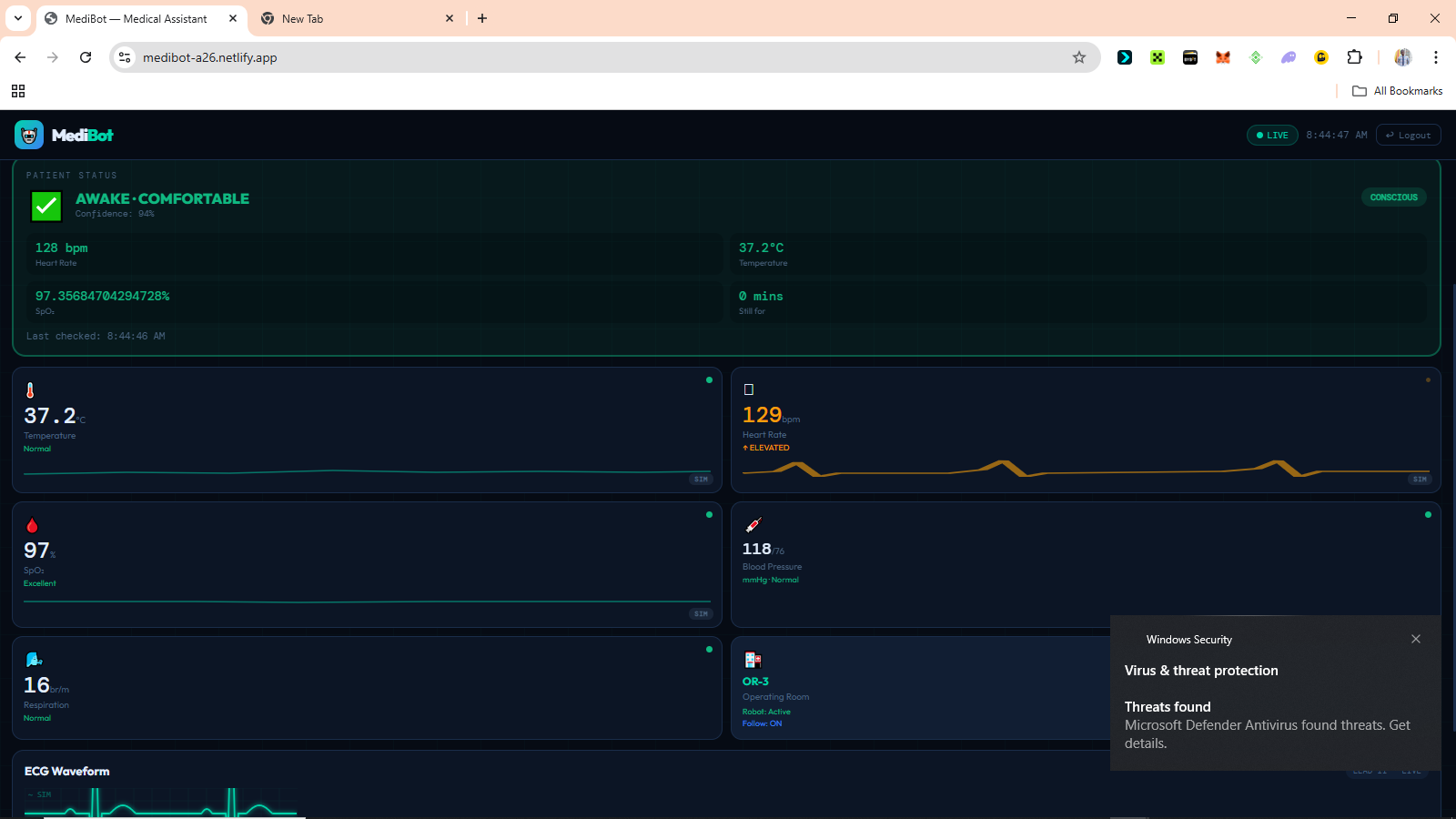
# MediBot: A Continuous AI Patient Monitoring System for Nigerian Hospitals ## Introduction Every day in Nigerian hospital wards, doctors and nurses make impossible choices. One nurse. Twenty patients. Eight hours. There's no way to watch everyone's health state at once. MediBot was built to change that, not by replacing nurses, but by giving them a system that never looks away. It is a continuous AI-powered patient monitoring system that combines embedded sensors, computer vision, edge machine learning, and a real-time web dashboard to detect when a patient needs attention before a crisis becomes irreversible. The entire system runs on affordable hardware that can be purchased locally in Nigeria, communicates through Supabase as its cloud backbone, and is accessible from any phone or laptop browser without any installation, making it deployable in hospitals that could never afford traditional ICU-grade monitoring equipment. --- ## The Problem ### The Monitoring Gap In most Nigerian hospital general wards, continuous bedside monitoring simply does not exist. A patient's oxygen saturation can fall from healthy to life-threatening in under two minutes. A patient losing consciousness may go unnoticed for twenty minutes or more if the nurse is responding to another emergency across the ward. Pain in sedated, post-operative, or non-verbal patients often goes completely undetected. Not because the staff does not care, but because no system is watching continuously enough to catch it. This is not an assumption. As of 2019, Nigeria had only 15 nurses and midwives per 10,000 patients [1], making continuous individual patient observation practically impossible in most general wards. A mixed-methods study conducted across three hospitals in Kenya found that during the 24 hours before a patient's death, respiratory rate was documented in only 1.2% of patient records, with insufficient monitoring equipment and high workload identified as the primary reasons nurses could not detect deterioration in time [2]. The WHO estimates that up to 134 million adverse events occur annually in hospitals across low and middle-income countries, with 83% of those events being preventable [3]. The problem is not the dedication of the people working in these hospitals. The problem is that the tools designed to close this gap were never built for these environments. ### Why Existing Solutions Do Not Fit ICU grade monitoring equipment exists. It works well. It costs millions of naira per unit, requires stable electricity, demands regular calibration by biomedical engineers, and was designed entirely around assumptions that do not match the realities of Nigerian general wards. The problem is not only funding. It is the design. Most medical monitoring technology was built for environments with completely different constraints. ### Why This Matters The consequences of the monitoring gap are measurable. Delayed response to cardiac events. Undetected respiratory decline. Unmanaged pain in post-operative patients. Missed early signs of fever escalation. Preventable deterioration during low-staffing periods. MediBot was built as a direct engineering response to that gap. Affordable, deployable, and designed around the realities that Nigerian healthcare workers actually operate in. --- ## What MediBot Does MediBot continuously monitors patients using a combination of medical sensors and AI vision. It classifies the patient's current condition in real-time and alerts medical staff when something requires attention. The system determines whether the patient is awake and comfortable, sleeping normally, in pain, showing signs of distress, potentially unconscious, or whether the bed is empty altogether. It achieves this by combining signals from multiple sources at the same time. | Signal | Source | |--------|--------| | Heart rate | MAX30102 sensor | | Blood oxygen saturation (SpO₂) | MAX30102 sensor | | Body temperature | MLX90614 infrared sensor | | Facial expression | AI vision | | Eye state (open or closed) | AI vision | | Body motion | Frame differencing | | Bed occupancy | ML object detection model | No single signal decides on its own. All signals are combined. The system is designed so that if one source fails, the others continue providing useful information. --- ## Components Used ### Hardware | Component | Purpose | |-----------|---------| | ESP32 Dev Module | Sensor reading, decision logic, alert management | | ESP32-CAM AI Thinker | Camera stream and ML vision inference | | MAX30102 | Heart rate and blood oxygen | | MLX90614 | Contactless infrared body temperature | | Active buzzer | Audible patient alerts | | Status LED | Visual connection indicator | ### Software and Platforms | Tool | Role | |------|------| | Arduino IDE and C++ | ESP32 firmware development | | Edge Impulse | ML model training and deployment | | TensorFlow Lite | On-device ML inference on ESP32-CAM | | face-api.js | Browser-based facial expression detection | | Supabase | Real-time database and authentication backend | | Netlify | Dashboard deployment | | Vanilla HTML, CSS, and JavaScript | Dashboard frontend | --- ## System Architecture MediBot uses a two-board architecture. The responsibilities are deliberately split between two ESP32 devices because of memory constraints that will be explained shortly. ``` ┌─────────────────────────────────────────────────────────┐ │ ESP32-CAM │ │ │ │ Bed Occupancy → Face Detection → Expression Model │ │ → Eye State Model │ │ → Motion Detection │ │ │ │ Sends JSON result via UART │ └──────────────────────────┬──────────────────────────────┘ │ GPIO16 ┌──────────────────────────▼──────────────────────────────┐ │ ESP32 Dev Module │ │ │ │ MAX30102 + MLX90614 → Patient State Engine │ │ → Posts to Supabase every 3s │ │ → Buzzer and Status LED │ └──────────────────────────┬──────────────────────────────┘ │ Supabase DB │ ┌──────────────────────────▼──────────────────────────────┐ │ Doctor Dashboard (Netlify PWA) │ │ Vitals · Patient State · Emotion · Alerts · Camera │ │ Works on phone, tablet, and laptop. No installation. │ └─────────────────────────────────────────────────────────┘ ``` The reason for two boards comes down to memory. The standard ESP32 has 520KB of RAM. Running WiFi, sensor reads, decision logic, and TFLite models simultaneously would exceed that. The ESP32-CAM adds 4MB of PSRAM, which makes it capable of running multiple vision models sequentially. Splitting responsibilities keeps each board well within its limits while the overall system stays powerful. --- ## How It Works ### Step 1: Bed Occupancy Check The ESP32-CAM runs a bed occupancy detection model on every frame. If the bed is confirmed empty and no vital signs have been detected for 60 seconds, all monitoring is suspended. This is what prevents false alerts in an empty ward. ### Step 2: Vital Signs Collection The ESP32 Dev reads heart rate and SpO₂ from the MAX30102, and body temperature from the MLX90614 every two seconds. A rolling average smooths out sensor noise. Temperature alerts only fire after a reading has been abnormal for ten continuous seconds, which prevents single-spike false alarms from triggering the system unnecessarily. ### Step 3: Vision Analysis The ESP32-CAM processes the camera feed through a sequential model pipeline. Each model only runs if the previous one confirms its precondition. If no face is detected, the expression model is skipped entirely. This saves compute and prevents false classifications. ``` Frame → Occupancy model → Face detection → Expression classifier → Eye state ``` ### Step 4: Patient State Decision The ESP32 Dev combines all signals using a layered decision engine. Emergency logic always runs first, before anything else. ``` Layer 1 — Emergency (runs first, every cycle) Critical HR or SpO₂ or temperature → EMERGENCY Layer 2 — Face visible Eyes open + normal expression + normal vitals → AWAKE, comfortable Eyes open + pain expression + abnormal vitals → IN PAIN (confirmed) Eyes open + pain expression + normal vitals → IN PAIN (confirm manually) Eyes closed + normal vitals + low motion → SLEEPING, well Eyes closed + abnormal vitals → SLEEPING, possible pain Layer 3 — Face not visible HR variance low + HR under 70 + normal vitals → LIKELY SLEEPING High motion + abnormal vitals → DISTRESS suspected Any critical vital → ALERT regardless ``` When the patient is facing away from the camera and no face can be detected, the system does not give up. It uses heart rate variance to estimate whether the patient is sleeping. During sleep, the heart rate drops and becomes more regular. Low variance combined with a low resting heart rate is a clinically established indicator of sleep, and MediBot uses it as a fallback when vision fails. ### Step 5: Alerts The buzzer provides immediate local feedback that works even when the doctor is not looking at the dashboard. | Patient State | Buzzer Behaviour | |---------------|-----------------| | System alive, patient stable | Beep every 2 seconds | | Patient confirmed sleeping | Silent, watching quietly | | Alert confirmed | Beep every 500ms | | Emergency | Beep every 150ms | | WiFi not connected | Silent | The dashboard simultaneously receives all data and displays timestamped alerts. ### Step 6: Dashboard The doctor views the dashboard from their phone anywhere on the same network. It shows live vitals, patient state, expression, and eye state from the camera, pain score, PPG waveform, alert history, and the camera feed. --- ## The Dashboard The dashboard is a Progressive Web App. It runs on any mobile or desktop browser with no installation needed. It was designed mobile-first because phones are the most accessible computing devices in Nigerian clinical settings. ### Camera Mode Switching One of the things I am most proud of in MediBot is the ability to switch the vision source at runtime directly from the dashboard. | Mode | How it works | |------|-------------| | Phone | face-api.js runs in the browser. Any smartphone becomes the AI vision system. | | ESP32-CAM | The hardware camera runs all ML models on-device via TensorFlow Lite. | | None | Vitals-only monitoring. Emergencies are still detected from sensor data alone. | When the mode is changed on the dashboard, the ESP32 reads the update from the database within fifteen seconds and automatically adjusts its data source. No reflashing. No reconfiguring. Just a button tap. ### Security Login credentials are stored in the database. There are no passwords anywhere in the source code. Row-level security is enabled on all database tables. Sessions clear automatically when the browser tab closes. Accounts are role-based for doctors, nurses, and administrators. --- ## The Machine Learning Pipeline All vision models run on the ESP32-CAM using Edge Impulse and TensorFlow Lite. | Model | Type | Input | Output | Status | |-------|------|-------|--------|--------| | Bed occupancy | FOMO object detection | Full frame 96×96 | occupied or empty | In training | | Face detection | FOMO pretrained | Full frame 96×96 | Face bounding box | Ready | | Expression classifier | MobileNetV1 0.25 | Face crop 96×96 | pain, neutral, happy, sad | In training | | Eye state classifier | MobileNetV1 0.1 | Eye crop 48×48 | open or closed | Planned | | Motion detection | Frame differencing | Frame delta | high, low, or none | Complete | FOMO was chosen specifically because it was designed for microcontrollers. Standard object detectors like YOLO take three to five seconds per inference on the ESP32-CAM. FOMO runs in approximately 200ms on the same hardware. For real-time patient monitoring, that difference matters enormously. ### Expression Dataset Training data for the expression classifier comes from FER2013 with over 35,000 facial expression images, the MRL Eye Dataset with over 84,000 open and closed eye images, and custom photos taken specifically for this project. The custom photos were the most important part. Most public datasets use front-facing photos taken in controlled environments. In a hospital bed, the camera might be overhead, mounted on a wall, in a corner, or close to the patient at bed level. A model trained only on face-level photos performs poorly on overhead views of someone lying down. The custom dataset was collected from all angles that match real deployment. --- ## Code Samples ### False alarm prevention using a confirmation streak A single abnormal reading is not clinically significant. This logic requires three consecutive abnormal cycles before confirming any alert. ```cpp #define CONFIRM_CYCLES 3 int abnormalStreak = 0; bool alertActive = false; void updateAlertConfirmation(bool abnormal) { if (abnormal) { abnormalStreak++; } else { abnormalStreak = 0; alertActive = false; } if (abnormalStreak >= CONFIRM_CYCLES) { alertActive = true; Serial.println("Alert confirmed"); } } ``` ### Temperature stability window Temperature only flags after ten continuous seconds of abnormal readings. ```cpp #define TEMP_VALID_MIN 35.0f #define TEMP_STABLE_MS 10000 unsigned long tempLowSince = 0; bool tempLowFlag = false; void checkTempStability(float avgTemp) { unsigned long now = millis(); if (avgTemp < TEMP_VALID_MIN) { if (tempLowSince == 0) tempLowSince = now; if (now - tempLowSince >= TEMP_STABLE_MS) { tempLowFlag = true; } } else { tempLowSince = 0; tempLowFlag = false; } } ``` ### Sleep detection from heart rate variance When the patient faces away from the camera, the system uses heart rate variance to infer sleep state. ```cpp float hrVariance = 0.0f; int hrHistory[10]; int hrCount = 0; void updateHRVariance(int hr) { hrHistory[hrCount % 10] = hr; hrCount++; float mean = 0; int n = min(hrCount, 10); for (int i = 0; i < n; i++) mean += hrHistory[i]; mean /= n; float variance = 0; for (int i = 0; i < n; i++) variance += pow(hrHistory[i] - mean, 2); hrVariance = variance / n; } bool isLikelySleeping(int hr, int spo2) { bool lowHR = hr > 0 && hr < 70; bool stableHR = hrVariance < 25.0f; bool normalSpO2 = spo2 == 0 || spo2 >= 94; return lowHR && stableHR && normalSpO2; } ``` ### Non-blocking buzzer state machine The buzzer never blocks the main loop. It goes silent during confirmed sleep but immediately resumes if distress is detected. ```cpp #define BUZZER_PIN 18 unsigned long lastBuzzTime = 0; bool buzzerOn = false; void updateBuzzer(bool wifiOK, bool sleeping) { unsigned long now = millis(); if (!wifiOK) { digitalWrite(BUZZER_PIN, LOW); return; } int interval, duration; if (emergencyConfirmed) { interval = 150; duration = 100; } else if (alertActive) { interval = 500; duration = 80; } else if (sleeping) { digitalWrite(BUZZER_PIN, LOW); return; } else { interval = 2000; duration = 60; } if (!buzzerOn && now - lastBuzzTime >= (unsigned long)interval) { digitalWrite(BUZZER_PIN, HIGH); buzzerOn = true; lastBuzzTime = now; } if (buzzerOn && now - lastBuzzTime >= (unsigned long)duration) { digitalWrite(BUZZER_PIN, LOW); buzzerOn = false; } } ``` ### Clinical expression mapping in the dashboard Seven raw emotion outputs from face-api.js are simplified to four labels that are actually meaningful in a clinical context. ```javascript const CLINICAL_EXPR = { pain: { icon: '😣', label: 'Pain', color: '#ef4444' }, disgusted: { icon: '😣', label: 'Pain', color: '#ef4444' }, fearful: { icon: '😣', label: 'Pain', color: '#ef4444' }, angry: { icon: '😠', label: 'Pain', color: '#ef4444' }, happy: { icon: '😊', label: 'Happy', color: '#10b981' }, neutral: { icon: '😐', label: 'Neutral', color: '#4a6480' }, sad: { icon: '😢', label: 'Sad', color: '#f59e0b' }, }; ``` ### Merging two independent data sources in the dashboard The dashboard reads sensor vitals from the ESP32 and expression data from the phone camera simultaneously, then merges them correctly. ```javascript async function fetchLatestData() { const [espRes, phoneRes] = await Promise.all([ fetch(VITALS_URL + '?source=eq.esp32&order=created_at.desc&limit=1', { headers }), fetch(VITALS_URL + '?source=eq.phone_camera&order=created_at.desc&limit=1', { headers }) ]); const esp = (await espRes.json())[0]; const phone = phoneRes.ok ? (await phoneRes.json())[0] : null; const phoneAge = phone ? (Date.now() - new Date(phone.created_at).getTime()) / 1000 : 999; const phoneFresh = phoneAge < 30 && phone?.emotion !== 'unknown'; return { ...esp, emotion: phoneFresh ? phone.emotion : esp.emotion, eyes: phoneFresh ? phone.eyes : esp.eyes, pain_score: phoneFresh ? phone.pain_score : esp.pain_score, }; } ``` --- ## Challenges Faced ### Sensor Instability The MAX30102 is sensitive to finger placement, pressure, and ambient light. Small movements produce large reading fluctuations. The MLX90614 reads closer to room temperature when the patient is under a blanket or the sensor is not pointing directly at bare skin. The solution for both was moving average smoothing combined with the confirmation streak system. Sustained readings matter. Single spikes do not. ### Memory on the ESP32 Running WiFi, HTTPS, sensor reads, JSON serialisation, and multiple HTTP clients simultaneously on a device with 520KB of RAM required careful engineering. Making HTTP clients static so they are allocated once globally rather than on the stack for every call, and staggering requests so only one HTTP call fires per loop cycle, were what eventually made the system stable. ### Camera Angle vs Training Data This was one of the most practically important problems in the project. Public expression datasets are captured face level with the subject looking directly at the camera. A camera mounted above a hospital bed sees something completely different. A model trained only on face level photos performs poorly on overhead views of a lying patient. Building a custom dataset from the actual deployment angles was not optional. It was necessary. ### Programming the ESP32-CAM The ESP32-CAM has no USB-to-serial chip. Programming it required using the main ESP32 Dev Module as a programmer by bridging its EN pin to GND, crossing TX and RX lines, and holding IO0 to GND on the CAM during upload. This is not clearly documented anywhere and required significant troubleshooting to figure out. ### False Alarms in Early Testing In early testing, the buzzer fired constantly from single-spike readings. One abnormal HR reading was enough to trigger the entire alert system. The three-cycle confirmation streak was the fix. A reading must be abnormal for three consecutive cycles before any alert fires. This eliminated almost all false alarms without meaningfully slowing down response to real emergencies. ### Merging Two Independent Data Sources The dashboard reads from two independent sources simultaneously, such as the ESP32 posting sensor vitals and the phone camera posting vision results. Getting the merge logic right required timestamp comparison, freshness validation, and careful field prioritisation to make sure the correct source overwrites the correct fields without corrupting either dataset. --- ## Project Gallery 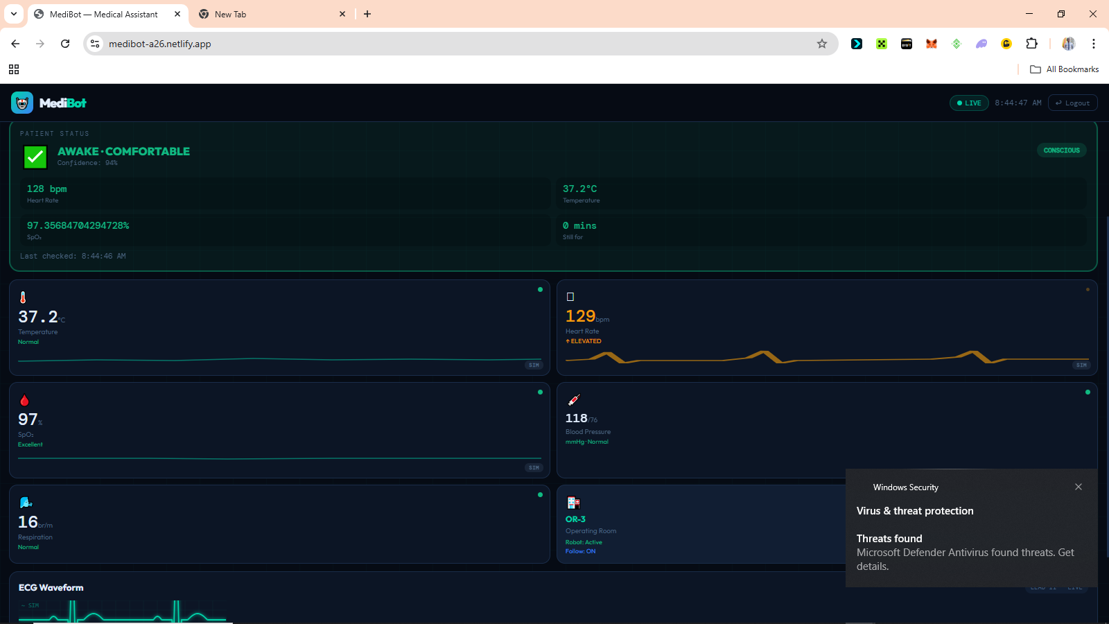 Vitals Overview 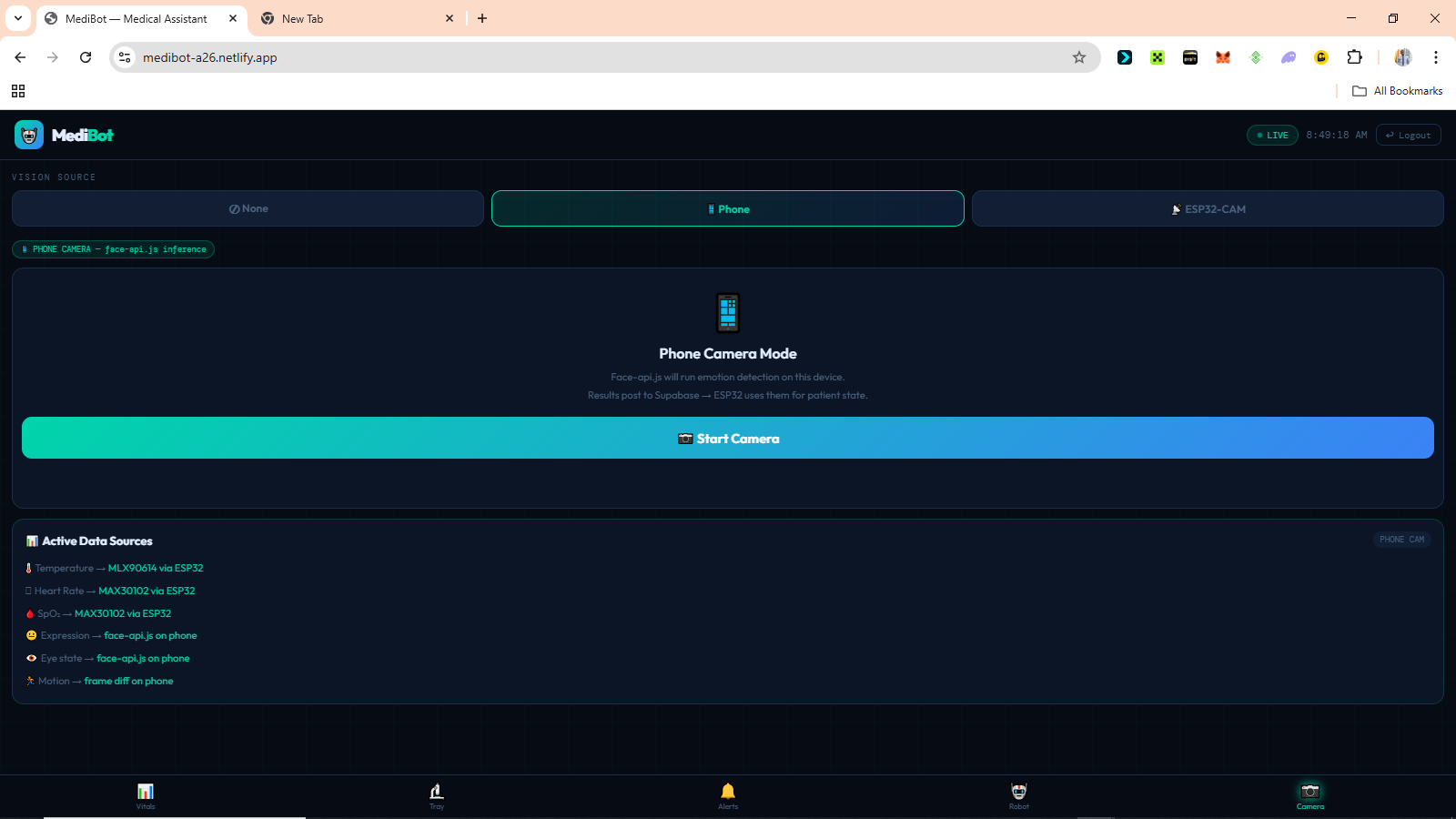 The Camera Connection page 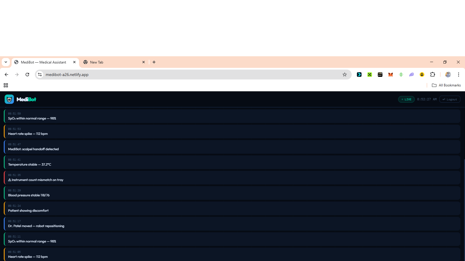 The Vital Evaluation Log page 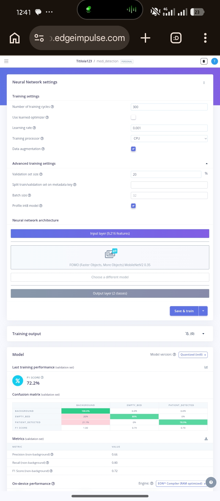 The Current Training Progress 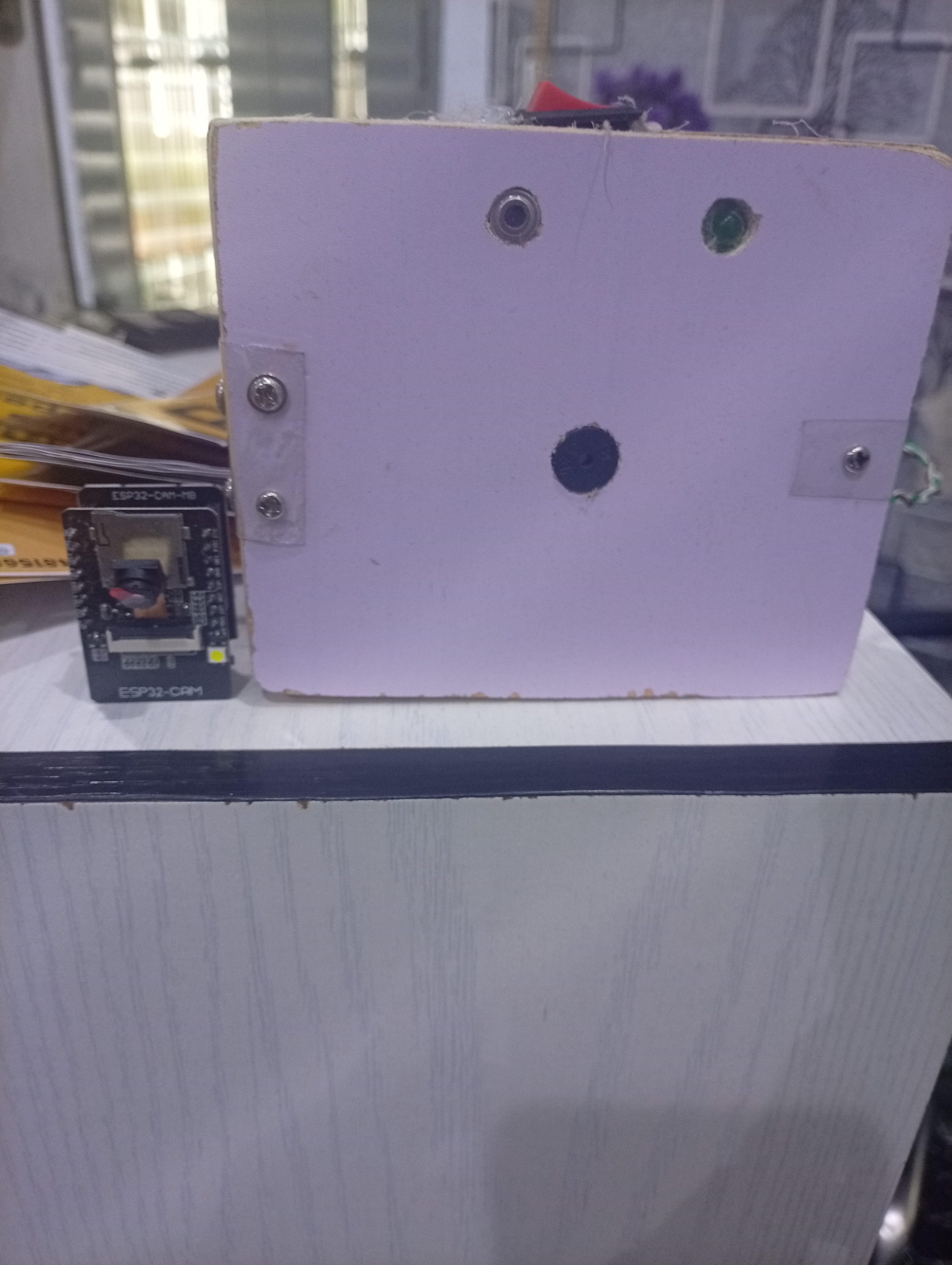 Medibot Device --- ## Current Status | Component | Status | |-----------|--------| | ESP32 vitals firmware | ✅ Complete | | MAX30102 HR and SpO₂ | ✅ Working | | MLX90614 temperature | ✅ Working | | Buzzer alert system | ✅ Complete | | Status LED | ✅ Complete | | Dashboard PWA | ✅ Deployed | | Login and role security | ✅ Complete | | Camera mode switching | ✅ Complete | | Real-time alert feed | ✅ Complete | | ESP32-CAM flashing | 🔄 In progress | | Bed occupancy model | 🔄 Training | | Expression classifier | 🔄 Dataset collection | | Eye state model | 📋 Planned | | Offline local mode | 📋 Planned | | Clinical validation | 📋 Planned | --- ## What Comes Next The immediate focus is on completing the ESP32-CAM vision pipeline, deploying the trained ML models to hardware, and beginning clinical validation in real patient environments. Long term, the goal is an offline-first version where the ESP32 hosts the dashboard locally so the entire system works without any internet connection. Hospitals with unreliable network access should not have to choose between monitoring and connectivity. --- ## Closing The monitoring gap in Nigerian hospitals is not only a funding problem. It is also an engineering problem, and engineering problems have engineering solutions. MediBot is one attempt at building that solution around the realities that actually exist here. Affordable hardware. Local components. Open-source software. Infrastructure hospitals already have. The talent to build these systems already exists in Nigeria. What has been missing is infrastructure, research continuity, and systems designed specifically for the environments where the need is real. --- ## References References [1] Runcie CW Chidebe et al. (2023). Brain Drain in Cancer Care: The Shrinking Clinical Oncology Workforce in Nigeria. Journal of Clinical Oncology. Available at pmc.ncbi.nlm.nih.gov/articles/PMC10752460 [2] Nickcy M. et al. (2024). General ward nurses detection and response to clinical deterioration in three hospitals at the Kenyan coast. BMC Nursing. Available at pmc.ncbi.nlm.nih.gov/articles/PMC10905788 [3] Peter M. Nthumba et al. cited in: Patient safety in a rural sub-Saharan Africa hospital. PLOS Global Public Health (2024). doi.org/10.1371/journal.pgph.0003919

Autonomous Delivery Robot with GPS Navigation & IoT Control.
Markdown Editor # Autonomous Delivery Robot (DeliBot) ## What I Built An end-to-end autonomous delivery robot system capable of GPS waypoint navigation, real-time remote control, and package tracking. The robot uses Ackermann steering geometry, a brushless motor, compass heading, and live MQTT communication to navigate to a destination autonomously. A Flask web app with WebSockets serves as the control dashboard — complete with user auth, delivery dispatch, email notifications, and a live tracking link for recipients. ## The Problem It Solves Large environments like university campuses, hospitals, and warehouses waste time and money on manual delivery. This robot provides a **low-cost, intelligent alternative** with autonomous navigation and remote monitoring. ## System Architecture The robot runs a continuous **Sense → Process → Decide → Move** loop: - **Sense** — GPS locks position; HMC5883L reads heading; ultrasonic detects obstacles - **Process** — ESP8266 calculates bearing error using Haversine formula - **Decide** — Proportional steering control adjusts servo angle - **Move** — Brushless ESC drives forward at controlled speed ## Hardware Stack - `ESP8266` — WiFi microcontroller (brain of the robot) - `NEO-6M GPS` — Real-world coordinate tracking - `HMC5883L Compass` — Heading estimation (calibrated for Lagos, Nigeria) - `Brushless Motor + ESC` — High-efficiency propulsion - `Servo Motor` — Ackermann steering angle control - `ESP32-CAM` — Live video streaming ## Navigation Algorithm ```cpp float bearingError = targetBearing - compassHeading; bearingError = normalizeAngle(bearingError); // -180 to +180 float steeringAngle = bearingError * (TURN_GAIN / 100.0); steeringAngle = constrain(steeringAngle, -45, 45); setSteeringAngle(steeringAngle); ``` The robot slows down for sharp turns (>30°) and stops within 5 meters of the waypoint. ## Software & Communication - **MQTT (HiveMQ broker)** — Lightweight real-time command/status channel - **Flask + SocketIO** — Backend with live WebSocket state push to dashboard - **SQLite** — Delivery records with tracking IDs - **Email Notifications** — Auto-sent to recipient with a unique tracking link ## Key Features - Autonomous GPS waypoint navigation - Manual control fallback (forward / backward / left / right / stop) - Real-time ETA calculation (Haversine distance ÷ 1.5 m/s) - Secure login/register with hashed passwords - Per-delivery tracking links with live robot dashboard - Delivery history admin panel ## Results A fully functional delivery robot that navigates autonomously to GPS coordinates, streams live video, and notifies recipients via email — built entirely with low-cost, accessible hardware.

 Robotics
45
Robotics
45
MediBot: A Continuous AI Patient Monitoring System for Nigerian Hospitals
# MediBot: A Continuous AI Patient Monitoring System for Nigerian Hospitals ## Introduction Every day in Nigerian hospital wards, doctors and nurses make impossible choices. One nurse. Twenty patients. Eight hours. There's no way to watch everyone's health state at once. MediBot was built to change that, not by replacing nurses, but by giving them a system that never looks away. It is a continuous AI-powered patient monitoring system that combines embedded sensors, computer vision, edge machine learning, and a real-time web dashboard to detect when a patient needs attention before a crisis becomes irreversible. The entire system runs on affordable hardware that can be purchased locally in Nigeria, communicates through Supabase as its cloud backbone, and is accessible from any phone or laptop browser without any installation, making it deployable in hospitals that could never afford traditional ICU-grade monitoring equipment. --- ## The Problem ### The Monitoring Gap In most Nigerian hospital general wards, continuous bedside monitoring simply does not exist. A patient's oxygen saturation can fall from healthy to life-threatening in under two minutes. A patient losing consciousness may go unnoticed for twenty minutes or more if the nurse is responding to another emergency across the ward. Pain in sedated, post-operative, or non-verbal patients often goes completely undetected. Not because the staff does not care, but because no system is watching continuously enough to catch it. This is not an assumption. As of 2019, Nigeria had only 15 nurses and midwives per 10,000 patients [1], making continuous individual patient observation practically impossible in most general wards. A mixed-methods study conducted across three hospitals in Kenya found that during the 24 hours before a patient's death, respiratory rate was documented in only 1.2% of patient records, with insufficient monitoring equipment and high workload identified as the primary reasons nurses could not detect deterioration in time [2]. The WHO estimates that up to 134 million adverse events occur annually in hospitals across low and middle-income countries, with 83% of those events being preventable [3]. The problem is not the dedication of the people working in these hospitals. The problem is that the tools designed to close this gap were never built for these environments. ### Why Existing Solutions Do Not Fit ICU grade monitoring equipment exists. It works well. It costs millions of naira per unit, requires stable electricity, demands regular calibration by biomedical engineers, and was designed entirely around assumptions that do not match the realities of Nigerian general wards. The problem is not only funding. It is the design. Most medical monitoring technology was built for environments with completely different constraints. ### Why This Matters The consequences of the monitoring gap are measurable. Delayed response to cardiac events. Undetected respiratory decline. Unmanaged pain in post-operative patients. Missed early signs of fever escalation. Preventable deterioration during low-staffing periods. MediBot was built as a direct engineering response to that gap. Affordable, deployable, and designed around the realities that Nigerian healthcare workers actually operate in. --- ## What MediBot Does MediBot continuously monitors patients using a combination of medical sensors and AI vision. It classifies the patient's current condition in real-time and alerts medical staff when something requires attention. The system determines whether the patient is awake and comfortable, sleeping normally, in pain, showing signs of distress, potentially unconscious, or whether the bed is empty altogether. It achieves this by combining signals from multiple sources at the same time. | Signal | Source | |--------|--------| | Heart rate | MAX30102 sensor | | Blood oxygen saturation (SpO₂) | MAX30102 sensor | | Body temperature | MLX90614 infrared sensor | | Facial expression | AI vision | | Eye state (open or closed) | AI vision | | Body motion | Frame differencing | | Bed occupancy | ML object detection model | No single signal decides on its own. All signals are combined. The system is designed so that if one source fails, the others continue providing useful information. --- ## Components Used ### Hardware | Component | Purpose | |-----------|---------| | ESP32 Dev Module | Sensor reading, decision logic, alert management | | ESP32-CAM AI Thinker | Camera stream and ML vision inference | | MAX30102 | Heart rate and blood oxygen | | MLX90614 | Contactless infrared body temperature | | Active buzzer | Audible patient alerts | | Status LED | Visual connection indicator | ### Software and Platforms | Tool | Role | |------|------| | Arduino IDE and C++ | ESP32 firmware development | | Edge Impulse | ML model training and deployment | | TensorFlow Lite | On-device ML inference on ESP32-CAM | | face-api.js | Browser-based facial expression detection | | Supabase | Real-time database and authentication backend | | Netlify | Dashboard deployment | | Vanilla HTML, CSS, and JavaScript | Dashboard frontend | --- ## System Architecture MediBot uses a two-board architecture. The responsibilities are deliberately split between two ESP32 devices because of memory constraints that will be explained shortly. ``` ┌─────────────────────────────────────────────────────────┐ │ ESP32-CAM │ │ │ │ Bed Occupancy → Face Detection → Expression Model │ │ → Eye State Model │ │ → Motion Detection │ │ │ │ Sends JSON result via UART │ └──────────────────────────┬──────────────────────────────┘ │ GPIO16 ┌──────────────────────────▼──────────────────────────────┐ │ ESP32 Dev Module │ │ │ │ MAX30102 + MLX90614 → Patient State Engine │ │ → Posts to Supabase every 3s │ │ → Buzzer and Status LED │ └──────────────────────────┬──────────────────────────────┘ │ Supabase DB │ ┌──────────────────────────▼──────────────────────────────┐ │ Doctor Dashboard (Netlify PWA) │ │ Vitals · Patient State · Emotion · Alerts · Camera │ │ Works on phone, tablet, and laptop. No installation. │ └─────────────────────────────────────────────────────────┘ ``` The reason for two boards comes down to memory. The standard ESP32 has 520KB of RAM. Running WiFi, sensor reads, decision logic, and TFLite models simultaneously would exceed that. The ESP32-CAM adds 4MB of PSRAM, which makes it capable of running multiple vision models sequentially. Splitting responsibilities keeps each board well within its limits while the overall system stays powerful. --- ## How It Works ### Step 1: Bed Occupancy Check The ESP32-CAM runs a bed occupancy detection model on every frame. If the bed is confirmed empty and no vital signs have been detected for 60 seconds, all monitoring is suspended. This is what prevents false alerts in an empty ward. ### Step 2: Vital Signs Collection The ESP32 Dev reads heart rate and SpO₂ from the MAX30102, and body temperature from the MLX90614 every two seconds. A rolling average smooths out sensor noise. Temperature alerts only fire after a reading has been abnormal for ten continuous seconds, which prevents single-spike false alarms from triggering the system unnecessarily. ### Step 3: Vision Analysis The ESP32-CAM processes the camera feed through a sequential model pipeline. Each model only runs if the previous one confirms its precondition. If no face is detected, the expression model is skipped entirely. This saves compute and prevents false classifications. ``` Frame → Occupancy model → Face detection → Expression classifier → Eye state ``` ### Step 4: Patient State Decision The ESP32 Dev combines all signals using a layered decision engine. Emergency logic always runs first, before anything else. ``` Layer 1 — Emergency (runs first, every cycle) Critical HR or SpO₂ or temperature → EMERGENCY Layer 2 — Face visible Eyes open + normal expression + normal vitals → AWAKE, comfortable Eyes open + pain expression + abnormal vitals → IN PAIN (confirmed) Eyes open + pain expression + normal vitals → IN PAIN (confirm manually) Eyes closed + normal vitals + low motion → SLEEPING, well Eyes closed + abnormal vitals → SLEEPING, possible pain Layer 3 — Face not visible HR variance low + HR under 70 + normal vitals → LIKELY SLEEPING High motion + abnormal vitals → DISTRESS suspected Any critical vital → ALERT regardless ``` When the patient is facing away from the camera and no face can be detected, the system does not give up. It uses heart rate variance to estimate whether the patient is sleeping. During sleep, the heart rate drops and becomes more regular. Low variance combined with a low resting heart rate is a clinically established indicator of sleep, and MediBot uses it as a fallback when vision fails. ### Step 5: Alerts The buzzer provides immediate local feedback that works even when the doctor is not looking at the dashboard. | Patient State | Buzzer Behaviour | |---------------|-----------------| | System alive, patient stable | Beep every 2 seconds | | Patient confirmed sleeping | Silent, watching quietly | | Alert confirmed | Beep every 500ms | | Emergency | Beep every 150ms | | WiFi not connected | Silent | The dashboard simultaneously receives all data and displays timestamped alerts. ### Step 6: Dashboard The doctor views the dashboard from their phone anywhere on the same network. It shows live vitals, patient state, expression, and eye state from the camera, pain score, PPG waveform, alert history, and the camera feed. --- ## The Dashboard The dashboard is a Progressive Web App. It runs on any mobile or desktop browser with no installation needed. It was designed mobile-first because phones are the most accessible computing devices in Nigerian clinical settings. ### Camera Mode Switching One of the things I am most proud of in MediBot is the ability to switch the vision source at runtime directly from the dashboard. | Mode | How it works | |------|-------------| | Phone | face-api.js runs in the browser. Any smartphone becomes the AI vision system. | | ESP32-CAM | The hardware camera runs all ML models on-device via TensorFlow Lite. | | None | Vitals-only monitoring. Emergencies are still detected from sensor data alone. | When the mode is changed on the dashboard, the ESP32 reads the update from the database within fifteen seconds and automatically adjusts its data source. No reflashing. No reconfiguring. Just a button tap. ### Security Login credentials are stored in the database. There are no passwords anywhere in the source code. Row-level security is enabled on all database tables. Sessions clear automatically when the browser tab closes. Accounts are role-based for doctors, nurses, and administrators. --- ## The Machine Learning Pipeline All vision models run on the ESP32-CAM using Edge Impulse and TensorFlow Lite. | Model | Type | Input | Output | Status | |-------|------|-------|--------|--------| | Bed occupancy | FOMO object detection | Full frame 96×96 | occupied or empty | In training | | Face detection | FOMO pretrained | Full frame 96×96 | Face bounding box | Ready | | Expression classifier | MobileNetV1 0.25 | Face crop 96×96 | pain, neutral, happy, sad | In training | | Eye state classifier | MobileNetV1 0.1 | Eye crop 48×48 | open or closed | Planned | | Motion detection | Frame differencing | Frame delta | high, low, or none | Complete | FOMO was chosen specifically because it was designed for microcontrollers. Standard object detectors like YOLO take three to five seconds per inference on the ESP32-CAM. FOMO runs in approximately 200ms on the same hardware. For real-time patient monitoring, that difference matters enormously. ### Expression Dataset Training data for the expression classifier comes from FER2013 with over 35,000 facial expression images, the MRL Eye Dataset with over 84,000 open and closed eye images, and custom photos taken specifically for this project. The custom photos were the most important part. Most public datasets use front-facing photos taken in controlled environments. In a hospital bed, the camera might be overhead, mounted on a wall, in a corner, or close to the patient at bed level. A model trained only on face-level photos performs poorly on overhead views of someone lying down. The custom dataset was collected from all angles that match real deployment. --- ## Code Samples ### False alarm prevention using a confirmation streak A single abnormal reading is not clinically significant. This logic requires three consecutive abnormal cycles before confirming any alert. ```cpp #define CONFIRM_CYCLES 3 int abnormalStreak = 0; bool alertActive = false; void updateAlertConfirmation(bool abnormal) { if (abnormal) { abnormalStreak++; } else { abnormalStreak = 0; alertActive = false; } if (abnormalStreak >= CONFIRM_CYCLES) { alertActive = true; Serial.println("Alert confirmed"); } } ``` ### Temperature stability window Temperature only flags after ten continuous seconds of abnormal readings. ```cpp #define TEMP_VALID_MIN 35.0f #define TEMP_STABLE_MS 10000 unsigned long tempLowSince = 0; bool tempLowFlag = false; void checkTempStability(float avgTemp) { unsigned long now = millis(); if (avgTemp < TEMP_VALID_MIN) { if (tempLowSince == 0) tempLowSince = now; if (now - tempLowSince >= TEMP_STABLE_MS) { tempLowFlag = true; } } else { tempLowSince = 0; tempLowFlag = false; } } ``` ### Sleep detection from heart rate variance When the patient faces away from the camera, the system uses heart rate variance to infer sleep state. ```cpp float hrVariance = 0.0f; int hrHistory[10]; int hrCount = 0; void updateHRVariance(int hr) { hrHistory[hrCount % 10] = hr; hrCount++; float mean = 0; int n = min(hrCount, 10); for (int i = 0; i < n; i++) mean += hrHistory[i]; mean /= n; float variance = 0; for (int i = 0; i < n; i++) variance += pow(hrHistory[i] - mean, 2); hrVariance = variance / n; } bool isLikelySleeping(int hr, int spo2) { bool lowHR = hr > 0 && hr < 70; bool stableHR = hrVariance < 25.0f; bool normalSpO2 = spo2 == 0 || spo2 >= 94; return lowHR && stableHR && normalSpO2; } ``` ### Non-blocking buzzer state machine The buzzer never blocks the main loop. It goes silent during confirmed sleep but immediately resumes if distress is detected. ```cpp #define BUZZER_PIN 18 unsigned long lastBuzzTime = 0; bool buzzerOn = false; void updateBuzzer(bool wifiOK, bool sleeping) { unsigned long now = millis(); if (!wifiOK) { digitalWrite(BUZZER_PIN, LOW); return; } int interval, duration; if (emergencyConfirmed) { interval = 150; duration = 100; } else if (alertActive) { interval = 500; duration = 80; } else if (sleeping) { digitalWrite(BUZZER_PIN, LOW); return; } else { interval = 2000; duration = 60; } if (!buzzerOn && now - lastBuzzTime >= (unsigned long)interval) { digitalWrite(BUZZER_PIN, HIGH); buzzerOn = true; lastBuzzTime = now; } if (buzzerOn && now - lastBuzzTime >= (unsigned long)duration) { digitalWrite(BUZZER_PIN, LOW); buzzerOn = false; } } ``` ### Clinical expression mapping in the dashboard Seven raw emotion outputs from face-api.js are simplified to four labels that are actually meaningful in a clinical context. ```javascript const CLINICAL_EXPR = { pain: { icon: '😣', label: 'Pain', color: '#ef4444' }, disgusted: { icon: '😣', label: 'Pain', color: '#ef4444' }, fearful: { icon: '😣', label: 'Pain', color: '#ef4444' }, angry: { icon: '😠', label: 'Pain', color: '#ef4444' }, happy: { icon: '😊', label: 'Happy', color: '#10b981' }, neutral: { icon: '😐', label: 'Neutral', color: '#4a6480' }, sad: { icon: '😢', label: 'Sad', color: '#f59e0b' }, }; ``` ### Merging two independent data sources in the dashboard The dashboard reads sensor vitals from the ESP32 and expression data from the phone camera simultaneously, then merges them correctly. ```javascript async function fetchLatestData() { const [espRes, phoneRes] = await Promise.all([ fetch(VITALS_URL + '?source=eq.esp32&order=created_at.desc&limit=1', { headers }), fetch(VITALS_URL + '?source=eq.phone_camera&order=created_at.desc&limit=1', { headers }) ]); const esp = (await espRes.json())[0]; const phone = phoneRes.ok ? (await phoneRes.json())[0] : null; const phoneAge = phone ? (Date.now() - new Date(phone.created_at).getTime()) / 1000 : 999; const phoneFresh = phoneAge < 30 && phone?.emotion !== 'unknown'; return { ...esp, emotion: phoneFresh ? phone.emotion : esp.emotion, eyes: phoneFresh ? phone.eyes : esp.eyes, pain_score: phoneFresh ? phone.pain_score : esp.pain_score, }; } ``` --- ## Challenges Faced ### Sensor Instability The MAX30102 is sensitive to finger placement, pressure, and ambient light. Small movements produce large reading fluctuations. The MLX90614 reads closer to room temperature when the patient is under a blanket or the sensor is not pointing directly at bare skin. The solution for both was moving average smoothing combined with the confirmation streak system. Sustained readings matter. Single spikes do not. ### Memory on the ESP32 Running WiFi, HTTPS, sensor reads, JSON serialisation, and multiple HTTP clients simultaneously on a device with 520KB of RAM required careful engineering. Making HTTP clients static so they are allocated once globally rather than on the stack for every call, and staggering requests so only one HTTP call fires per loop cycle, were what eventually made the system stable. ### Camera Angle vs Training Data This was one of the most practically important problems in the project. Public expression datasets are captured face level with the subject looking directly at the camera. A camera mounted above a hospital bed sees something completely different. A model trained only on face level photos performs poorly on overhead views of a lying patient. Building a custom dataset from the actual deployment angles was not optional. It was necessary. ### Programming the ESP32-CAM The ESP32-CAM has no USB-to-serial chip. Programming it required using the main ESP32 Dev Module as a programmer by bridging its EN pin to GND, crossing TX and RX lines, and holding IO0 to GND on the CAM during upload. This is not clearly documented anywhere and required significant troubleshooting to figure out. ### False Alarms in Early Testing In early testing, the buzzer fired constantly from single-spike readings. One abnormal HR reading was enough to trigger the entire alert system. The three-cycle confirmation streak was the fix. A reading must be abnormal for three consecutive cycles before any alert fires. This eliminated almost all false alarms without meaningfully slowing down response to real emergencies. ### Merging Two Independent Data Sources The dashboard reads from two independent sources simultaneously, such as the ESP32 posting sensor vitals and the phone camera posting vision results. Getting the merge logic right required timestamp comparison, freshness validation, and careful field prioritisation to make sure the correct source overwrites the correct fields without corrupting either dataset. --- ## Project Gallery  Vitals Overview  The Camera Connection page  The Vital Evaluation Log page  The Current Training Progress  Medibot Device --- ## Current Status | Component | Status | |-----------|--------| | ESP32 vitals firmware | ✅ Complete | | MAX30102 HR and SpO₂ | ✅ Working | | MLX90614 temperature | ✅ Working | | Buzzer alert system | ✅ Complete | | Status LED | ✅ Complete | | Dashboard PWA | ✅ Deployed | | Login and role security | ✅ Complete | | Camera mode switching | ✅ Complete | | Real-time alert feed | ✅ Complete | | ESP32-CAM flashing | 🔄 In progress | | Bed occupancy model | 🔄 Training | | Expression classifier | 🔄 Dataset collection | | Eye state model | 📋 Planned | | Offline local mode | 📋 Planned | | Clinical validation | 📋 Planned | --- ## What Comes Next The immediate focus is on completing the ESP32-CAM vision pipeline, deploying the trained ML models to hardware, and beginning clinical validation in real patient environments. Long term, the goal is an offline-first version where the ESP32 hosts the dashboard locally so the entire system works without any internet connection. Hospitals with unreliable network access should not have to choose between monitoring and connectivity. --- ## Closing The monitoring gap in Nigerian hospitals is not only a funding problem. It is also an engineering problem, and engineering problems have engineering solutions. MediBot is one attempt at building that solution around the realities that actually exist here. Affordable hardware. Local components. Open-source software. Infrastructure hospitals already have. The talent to build these systems already exists in Nigeria. What has been missing is infrastructure, research continuity, and systems designed specifically for the environments where the need is real. --- ## References References [1] Anyasodor et al. (2023). Brain Drain in Cancer Care: The Shrinking Clinical Oncology Workforce in Nigeria. Journal of Clinical Oncology. Available at pmc.ncbi.nlm.nih.gov/articles/PMC10752460 [2] Kaluti D. et al. (2024). General ward nurses detection and response to clinical deterioration in three hospitals at the Kenyan coast. BMC Nursing. Available at pmc.ncbi.nlm.nih.gov/articles/PMC10905788 [3] Wilson et al. cited in: Patient safety in a rural sub-Saharan Africa hospital. PLOS Global Public Health (2024). doi.org/10.1371/journal.pgph.0003919
 IoT
54
IoT
54
Automated Precision Irrigation & Nutrient Management System
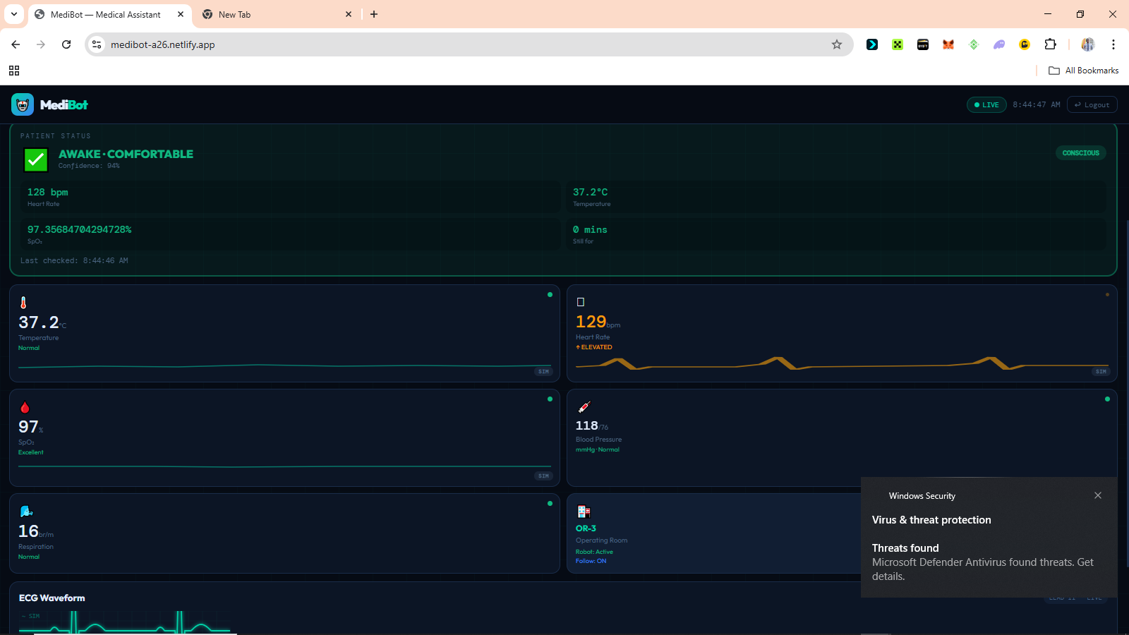
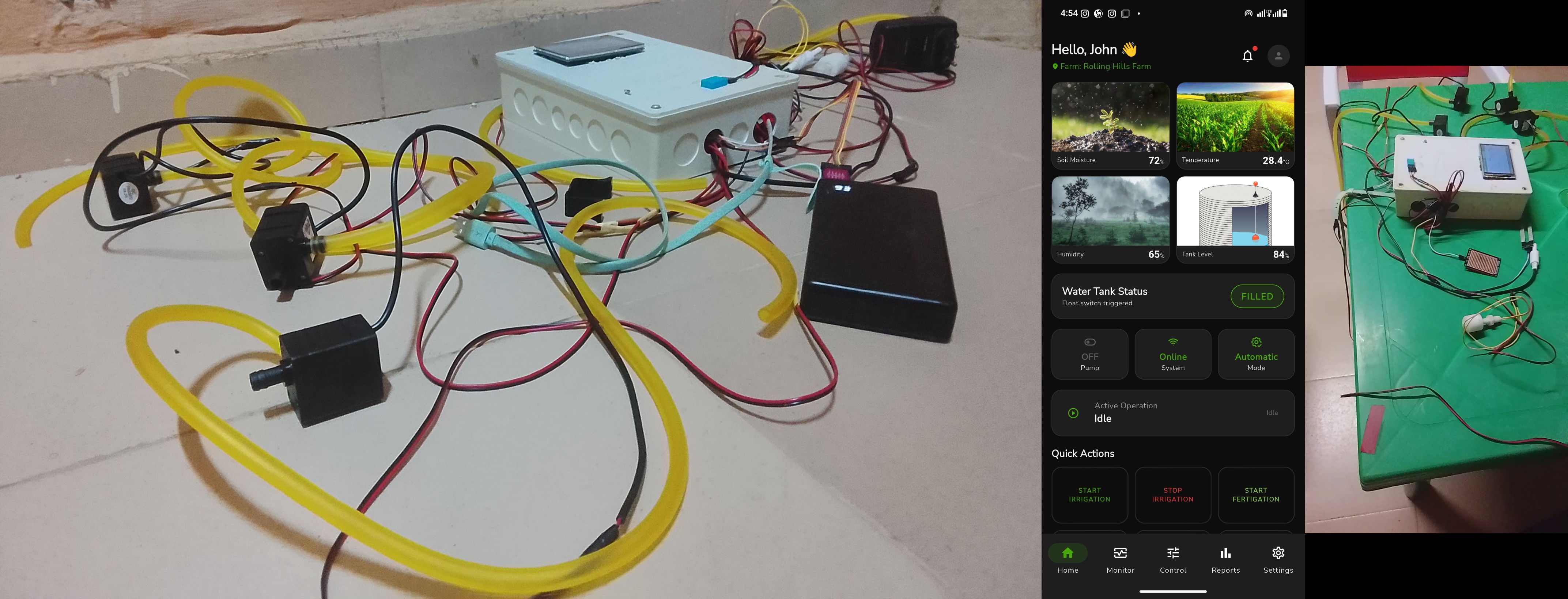
# Croppeak_ng ### Automated Precision Irrigation & Nutrient Management System --- ## What I Built A full-stack IoT system that automates farm irrigation and fertilizer delivery using real sensor data so farmers stop guessing and start growing smarter. The system reads soil moisture, temperature, humidity, and water levels from field sensors, makes intelligent decisions, and controls pumps and valves automatically, all manageable from a mobile app or web dashboard in real time. **Stack at a glance:** - **Hardware** : STM32 microcontroller + ESP832 WiFi module + soil, TDS, rain, flow sensors, relays and others - **Backend** : Appwrite (database, auth, realtime) + Next.js API - **Mobile** : Flutter app with BLoC state management - **Web** : Next.js dashboard with Mantine UI --- ## How It Works ``` Soil Sensor → STM32 reads data → ESP832 sends to cloud ↓ Appwrite stores + broadcasts in real time ↓ Automation engine checks rules (moisture low? rain detected?) ↓ Command sent → relay fires → pump or valve activates ↓ Farmer sees everything live on Flutter app or web dashboard ``` --- ## Results - **~38% reduction** in water usage vs. manual scheduling - **Zero manual fertigation** — NPK dosing handled automatically by TDS readings - Fault detection catches dry-runs and pump failures in **under 3 seconds** - Works **offline** - RTC keeps automation running even without internet --- *Croppeak_ng - Precision farming, built for the Nigerian field.*

 Robotics
48
Robotics
48
Autonomous Delivery Robot with GPS Navigation & IoT Control.
# Autonomous Delivery Robot (DeliBot) ## What I Built An end-to-end autonomous delivery robot system capable of GPS waypoint navigation, real-time remote control, and package tracking. The robot uses Ackermann steering geometry, a brushless motor, compass heading, and live MQTT communication to navigate to a destination autonomously. A Flask web app with WebSockets serves as the control dashboard — complete with user auth, delivery dispatch, email notifications, and a live tracking link for recipients. ## The Problem It Solves Large environments like university campuses, hospitals, and warehouses waste time and money on manual delivery. This robot provides a **low-cost, intelligent alternative** with autonomous navigation and remote monitoring. ## System Architecture The robot runs a continuous **Sense → Process → Decide → Move** loop: - **Sense** — GPS locks position; HMC5883L reads heading; ultrasonic detects obstacles - **Process** — ESP8266 calculates bearing error using Haversine formula - **Decide** — Proportional steering control adjusts servo angle - **Move** — Brushless ESC drives forward at controlled speed ## Hardware Stack - `ESP8266` — WiFi microcontroller (brain of the robot) - `NEO-6M GPS` — Real-world coordinate tracking - `HMC5883L Compass` — Heading estimation (calibrated for Lagos, Nigeria) - `Brushless Motor + ESC` — High-efficiency propulsion - `Servo Motor` — Ackermann steering angle control - `ESP32-CAM` — Live video streaming ## Navigation Algorithm ```cpp float bearingError = targetBearing - compassHeading; bearingError = normalizeAngle(bearingError); // -180 to +180 float steeringAngle = bearingError * (TURN_GAIN / 100.0); steeringAngle = constrain(steeringAngle, -45, 45); setSteeringAngle(steeringAngle); ``` The robot slows down for sharp turns (>30°) and stops within 5 meters of the waypoint. ## Software & Communication - **MQTT (HiveMQ broker)** — Lightweight real-time command/status channel - **Flask + SocketIO** — Backend with live WebSocket state push to dashboard - **SQLite** — Delivery records with tracking IDs - **Email Notifications** — Auto-sent to recipient with a unique tracking link ## Key Features - Autonomous GPS waypoint navigation - Manual control fallback (forward / backward / left / right / stop) - Real-time ETA calculation (Haversine distance ÷ 1.5 m/s) - Secure login/register with hashed passwords - Per-delivery tracking links with live robot dashboard - Delivery history admin panel ## Results A fully functional delivery robot that navigates autonomously to GPS coordinates, streams live video, and notifies recipients via email — built entirely with low-cost, accessible hardware.

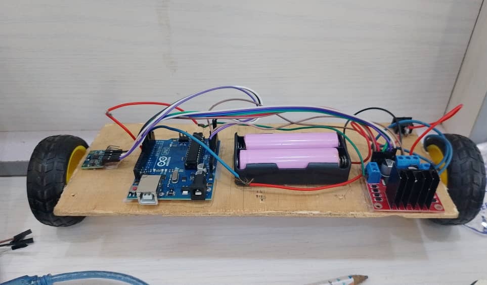 Robotics
55
Robotics
55
Two-Wheel Self-Balancing Robot with Real-Time PID Stabilization
# Two-Wheel Self-Balancing Robot with Real-Time PID Stabilization ## What I Built A two-wheeled self-balancing robot built using an Arduino Uno, MPU6050 IMU, and L298N motor driver. The robot stabilizes itself in real time using a PID controller and continuously corrects its tilt angle through motor speed adjustment. This project explores embedded systems, control theory, sensor feedback, and real-time motor control. --- ## Components Used * Arduino Uno * MPU6050 IMU * L298N Motor Driver * DC geared motors * Li-ion batteries --- ## Control System The robot behaves similarly to an inverted pendulum system where balance must be continuously maintained through feedback correction. The PID controller computes: ```text error = setpoint - angle ``` and generates a correction output using: ```text U = Kp·e + Ki·∑e + Kd·(de/dt) ``` The output determines motor direction and PWM speed. --- ## PID Values ```cpp kp = 30; ki = 0; kd = 6; ``` --- ## Challenges Faced * PID tuning instability * Motor response inconsistencies * Sensor noise and drift * One-sided balancing behavior * Calibration issues

2 Wheel Self-Balancing Car with ESP Cam for detection
<!DOCTYPE html> <html lang="en"> <head> <meta charset="UTF-8"> <meta name="viewport" content="width=device-width, initial-scale=1.0"> <title>Self-Balancing Robot Project</title> <style> body { margin: 0; font-family: 'Segoe UI', Tahoma, Geneva, Verdana, sans-serif; background: #0f172a; color: #e2e8f0; } .container { max-width: 900px; margin: auto; padding: 40px 20px; } .card { background: #1e293b; border-radius: 16px; padding: 30px; box-shadow: 0 10px 30px rgba(0,0,0,0.4); } h1 { font-size: 2.5rem; margin-bottom: 10px; color: #38bdf8; } h2 { color: #94a3b8; margin-bottom: 20px; font-weight: 400; } p { line-height: 1.7; font-size: 1.05rem; color: #cbd5f5; } .highlight { color: #38bdf8; font-weight: 600; } .footer { margin-top: 30px; text-align: center; font-size: 0.9rem; color: #64748b; } .badge { display: inline-block; padding: 6px 12px; margin: 5px 5px 0 0; background: #334155; border-radius: 999px; font-size: 0.8rem; } </style> </head> <body> <div class="container"> <div class="card"> <h1>Two-Wheel Self-Balancing Robot</h1> <h2>With ESP Camera-Based Object Detection</h2> <p> This project presents a <span class="highlight">two-wheel self-balancing robotic system</span> designed using advanced control techniques and real-time sensor feedback. </p> <p> The robot maintains stability using a <span class="highlight">PID (Proportional-Integral-Derivative) control system</span>. Orientation data is collected through the <span class="highlight">MPU6050 gyroscope and accelerometer module</span>, which continuously measures the tilt angle of the system. </p> <p> The measured tilt is processed through the PID loop, which dynamically adjusts motor speed using <span class="highlight">PWM (Pulse Width Modulation)</span>. This ensures precise corrections, allowing the robot to remain balanced in real time. </p> <p> To enhance environmental interaction, an <span class="highlight">ESP Camera module</span> is integrated for <span class="highlight">color and object detection</span>. This enables the robot to respond intelligently to its surroundings while maintaining stability. </p> <p> Overall, this system combines <span class="highlight">control theory, embedded systems, and computer vision</span> to create a responsive and autonomous balancing robot. </p> <div> <span class="badge">PID Control</span> <span class="badge">MPU6050</span> <span class="badge">ESP-CAM</span> <span class="badge">Computer Vision</span> <span class="badge">PWM Motor Control</span> </div> <div class="footer"> Project by Jubril Badmos </div> </div> </div> </body> </html>

2 Wheel Self-Balancing Car with ESP Cam for detection
<!DOCTYPE html> <html lang="en"> <head> <meta charset="UTF-8"> <meta name="viewport" content="width=device-width, initial-scale=1.0"> <title>Self-Balancing Robot Project</title> <style> body { margin: 0; font-family: 'Segoe UI', Tahoma, Geneva, Verdana, sans-serif; background: #0f172a; color: #e2e8f0; } .container { max-width: 900px; margin: auto; padding: 40px 20px; } .card { background: #1e293b; border-radius: 16px; padding: 30px; box-shadow: 0 10px 30px rgba(0,0,0,0.4); } h1 { font-size: 2.5rem; margin-bottom: 10px; color: #38bdf8; } h2 { color: #94a3b8; margin-bottom: 20px; font-weight: 400; } p { line-height: 1.7; font-size: 1.05rem; color: #cbd5f5; } .highlight { color: #38bdf8; font-weight: 600; } .footer { margin-top: 30px; text-align: center; font-size: 0.9rem; color: #64748b; } .badge { display: inline-block; padding: 6px 12px; margin: 5px 5px 0 0; background: #334155; border-radius: 999px; font-size: 0.8rem; } </style> </head> <body> <div class="container"> <div class="card"> <h1>Two-Wheel Self-Balancing Robot</h1> <h2>With ESP Camera-Based Object Detection</h2> <p> This project presents a <span class="highlight">two-wheel self-balancing robotic system</span> designed using advanced control techniques and real-time sensor feedback. </p> <p> The robot maintains stability using a <span class="highlight">PID (Proportional-Integral-Derivative) control system</span>. Orientation data is collected through the <span class="highlight">MPU6050 gyroscope and accelerometer module</span>, which continuously measures the tilt angle of the system. </p> <p> The measured tilt is processed through the PID loop, which dynamically adjusts motor speed using <span class="highlight">PWM (Pulse Width Modulation)</span>. This ensures precise corrections, allowing the robot to remain balanced in real time. </p> <p> To enhance environmental interaction, an <span class="highlight">ESP Camera module</span> is integrated for <span class="highlight">color and object detection</span>. This enables the robot to respond intelligently to its surroundings while maintaining stability. </p> <p> Overall, this system combines <span class="highlight">control theory, embedded systems, and computer vision</span> to create a responsive and autonomous balancing robot. </p> <div> <span class="badge">PID Control</span> <span class="badge">MPU6050</span> <span class="badge">ESP-CAM</span> <span class="badge">Computer Vision</span> <span class="badge">PWM Motor Control</span> </div> <div class="footer"> Project by Jubril Badmos </div> </div> </div> </body> </html>
 Robotics
48
Robotics
48
Smart Security Box: A Cloud-Connected IoT Access Control System
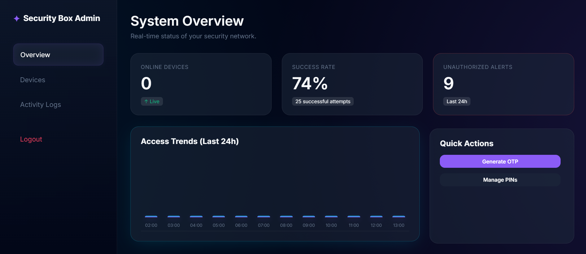
# Smart Security Box ## What I Built A cloud-connected IoT security system built around the ESP32 microcontroller. It features a physical keypad and LCD display for PIN entry, a solenoid lock for access control, and a live web dashboard for remote monitoring and management — all backed by a Flask API deployed on Render.com and a Supabase (PostgreSQL) cloud database. ## Why It Matters Traditional safes are offline and offer zero visibility. Smart alternatives are expensive and closed-source. This project bridges that gap — providing a **fully open, globally accessible** security system with real-time audit logs, dynamic OTPs, and an admin dashboard you can access from anywhere. ## How It Works The system runs on three layers: 1. **The Edge (Hardware)** — ESP32 reads keypad input and sends a secure HTTPS request to the cloud. Falls back to a Master PIN if offline. 2. **The Brain (Cloud API)** — Flask API verifies PINs against the database, manages OTPs, and tracks all access events. 3. **The Control Room (Dashboard)** — A glassmorphism web UI where admins log in to view live access charts, generate OTPs, and manage devices. ## Problems Encountered & Solutions | Problem | Solution | |---|---| | **Keypad Ghost Inputs**: GPIO conflicts caused missed or repeated key presses | Rewired Row 2: GPIO 2 → GPIO 27 and Col 2: GPIO 5 → GPIO 12 to eliminate hardware interference | | **Server Connectivity Failure**: ESP32 hung indefinitely when Wi-Fi dropped | Implemented a Heartbeat system + Offline Master PIN fallback | | **Complex Cloud Deployment**: Manual Python environment setup was error-prone | Wrote a `render.yaml` Infrastructure-as-Code file to fully automate the build | | **UX Friction**: Email login felt impersonal | Refactored entire auth system to use custom Usernames | ## Key Features - Dynamic OTP generation with expiry - Real-time access log with Chart.js trend visualization - JWT-secured admin dashboard - Offline fallback mode for uninterrupted access - Full audit trail of every PIN attempt (success or failure) ## What I Used and Why - **ESP32** — Built-in Wi-Fi, dual-core, handles real-time input without lag - **Flask (Python)** — Lightweight, fast API with minimal overhead - **Supabase (PostgreSQL)** — Scalable, secure, real-time cloud database - **JWT** — Stateless, secure admin session management - **Vanilla CSS (Glassmorphism)** — Custom premium aesthetic, no bloated frameworks - **Render.com** — Zero-config cloud deployment with free HTTPS ## Milestones 1. Hardware assembled and tested (Keypad + LCD + ESP32 + Lock) 2. ESP32 communicating with local Flask server 3. Data migrated to Supabase cloud database 4. Full web admin dashboard built with live charts 5. Deployed live on Render.com with global HTTPS access ## The Road Ahead - **Biometric Auth** — Fingerprint scanner for triple-factor security - **Mobile Alerts** — Telegram/WhatsApp push notifications on failed attempts - **Battery Mode** — ESP32 Deep Sleep for portable, long-term deployment - **Multi-Device** — Manage multiple boxes from one dashboard - **AI Threat Detection** — Flag unusual access patterns automatically ```javascript // Live Heartbeat Simulator const deviceId = "DEVICE_001"; let logs = []; function simulateHeartbeat() { const timestamp = new Date().toLocaleTimeString(); const status = Math.random() > 0.1 ? "✅ ONLINE" : "⚠️ WARNING"; logs.unshift(`[${timestamp}] ${deviceId}: ${status}`); if (logs.length > 5) logs.pop(); console.clear(); console.log("=== SMART SECURITY BOX MONITOR ==="); logs.forEach(log => console.log(log)); } setInterval(simulateHeartbeat, 3000); simulateHeartbeat();

 Robotics
123
Robotics
123
MediBot: A Continuous AI-Powered Patient Monitoring for Hospitals.
# MediBot: A Continuous AI-Powered Patient Monitoring for Hospitals. ## The Problem In many Nigerian hospital wards, one nurse monitors between 10 and 20 patients at the same time. That is not negligence. That is the reality of what the healthcare system has to work with. The consequence is a monitoring gap that no amount of dedication can close by hand. Oxygen saturation can fall from a healthy level to a life-threatening one in under two minutes. A patient losing consciousness may go unnoticed for 20 minutes or more if the nurse is attending to another emergency. Pain in sedated or non-verbal patients often goes completely undetected because there is simply no continuous system watching closely enough. The standard solution to this problem costs millions of naira per ward. ICU-grade monitors are expensive, difficult to maintain, and built around assumptions that do not match the realities of many Nigerian hospitals. MediBot was built around those realities from the beginning. The goal was never to build another expensive hospital machine. The goal was to build a system that could realistically exist in Nigerian hospitals using affordable hardware, open-source software, and infrastructure that hospitals already have access to. --- ## What MediBot Does MediBot continuously monitors patients without requiring a nurse to remain physically at the bedside. The system combines: - Contactless temperature monitoring - Heart rate monitoring - Blood oxygen saturation monitoring - AI-powered facial analysis - Pain detection - Eye-state analysis - Real-time patient state classification - Remote dashboard monitoring to determine what condition the patient is likely in at any given moment. When everything is stable, the system stays quiet and keeps watching. When something becomes dangerous, it alerts medical staff immediately. The purpose is not to replace nurses or doctors. The purpose is to help them see more patients safely with the limited manpower already available. --- ## Why Contactless Monitoring Matters One of the biggest focuses of MediBot is contactless monitoring. Many hospital systems only react when a patient manually reports distress or when a nurse physically checks them. That creates long periods where deterioration can happen unnoticed. MediBot reduces that gap by continuously observing the patient using both sensors and AI vision. The MLX90614 infrared sensor measures temperature without touching the patient. The camera system continuously watches facial expressions, eye state, and movement patterns. The AI models estimate pain levels and determine whether the patient appears awake, asleep, distressed, or unconscious. The only contact-based sensor currently in the system is the MAX30102 pulse oximeter used for heart rate and blood oxygen saturation monitoring. That decision was not because a contactless approach was preferred less. It was because a reliable and affordable contactless alternative that could realistically be sourced locally in Nigeria was not available during development. Rather than delay the entire system waiting for hardware that may be difficult or expensive to obtain locally, the project prioritised building a working monitoring pipeline around components that could actually be sourced and deployed within the Nigerian ecosystem. Everything else in the monitoring pipeline was intentionally designed to minimise physical interaction with the patient as much as possible. This matters especially in situations where patients: - Cannot communicate clearly - Are sedated - Are unconscious - Are post-operative - Are critically ill - Are being monitored remotely The system keeps watching even when nobody else can. --- ## Innovation Built Around Nigerian Realities Most medical monitoring systems are designed for hospitals with stable electricity, strong internet infrastructure, large budgets, and dedicated biomedical engineering teams. MediBot was designed around the opposite assumptions. That constraint shaped every engineering decision in the system. --- ## Low-Cost Embedded AI The entire system runs on ESP32 hardware costing only a fraction of traditional hospital monitoring equipment. Instead of requiring expensive GPUs or cloud servers, MediBot pushes intelligence directly onto embedded devices. The ESP32 handles: - Sensor readings - Patient-state logic - Alert management - Communication with the dashboard while the vision system handles AI inference separately. This two-board architecture exists because memory is the real constraint. Splitting responsibilities across devices allows the system to remain responsive while still running AI models and live monitoring simultaneously. --- ## Browser-Based AI Vision One of the most important innovations in MediBot is the browser-based AI vision pipeline. Instead of requiring expensive dedicated AI hardware, the current production prototype uses a smartphone camera running `face-api.js` directly inside the browser. That means: - No cloud inference - No GPU server - No installation - No expensive AI workstation A regular smartphone becomes the AI vision system. The browser continuously performs: - Face detection - Expression classification - Eye-state detection - Pain estimation and sends those results directly into the patient-state engine. This is important because smartphones are already widely available in Nigerian hospitals. MediBot turns existing devices into clinical monitoring tools instead of requiring hospitals to buy entirely new infrastructure. ```javascript // Browser-based AI vision pipeline using face-api.js const dets = await faceapi .detectAllFaces( vid, new faceapi.TinyFaceDetectorOptions({ inputSize: 224, scoreThreshold: 0.4 }) ) .withFaceLandmarks(true) .withFaceExpressions(); // Smooth emotion scores across frames Object.keys(phoneExprBuf).forEach(k => { phoneExprBuf[k].push(expr[k] || 0); if (phoneExprBuf[k].length > PHONE_SMOOTH) { phoneExprBuf[k].shift(); } }); // Weighted pain score estimation let pain = 0; Object.keys(PAIN_W).forEach(e => { pain += (smoothed[e] || 0) * PAIN_W[e]; }); pain = Math.round( Math.max(0, Math.min(100, pain * 160)) ); // Eye state detection using Eye Aspect Ratio const avgEAR = (ear(left) + ear(right)) / 2; eyeState = avgEAR < 0.22 ? 'closed' : 'open'; ``` --- ## Designed for Usefulness, Not Demonstration Many prototypes work only in ideal conditions. MediBot was built around usefulness first. The system focuses heavily on: - Fast deployment - Reliability - Low hardware cost - Low bandwidth usage - Minimal maintenance - Real-time usefulness The dashboard works on phones because phones are the most available computing devices in many wards. The alert system runs independently of the dashboard because internet access cannot always be trusted. The vision system continues running locally even during network instability. Every part of the system was designed around making sure it remains clinically useful under imperfect conditions. --- ## Reading the Patient MediBot combines multiple forms of monitoring together because no single signal is reliable enough on its own. The system reads: - Heart rate - Blood oxygen saturation - Temperature - Facial expression - Eye state - Motion patterns and combines them to determine what state the patient is likely in. The patient-state engine classifies conditions such as: - Awake - Sleeping - Distressed - In pain - Unconscious - Critical emergency Emergency logic always runs first. If vitals become critically dangerous, the system immediately escalates regardless of what the camera sees. ```cpp // Emergency classification logic bool hrCritical = hrPresent && (hr < 30 || hr > 150); bool spo2Critical = spo2Present && (spo2 < 85); bool tempCritical = tempPresent && (tempStable < 34.0f || tempStable > 41.0f); if (hrCritical || spo2Critical || tempCritical) { patientState = "unconscious"; distressLevel = "CRITICAL"; painScore = 100; return; } ``` When vitals are stable, the AI vision system helps determine whether the patient appears comfortable, asleep, or in visible distress. --- ## Sensor Detection and Reliability The firmware scans the I2C bus during startup and confirms which sensors are connected before monitoring begins. This makes hardware debugging significantly easier in real deployment environments. ```cpp // Boot-time I2C sensor scan void scanI2CBus() { for (byte addr = 1; addr < 127; addr++) { Wire.beginTransmission(addr); if (Wire.endTransmission() == 0) { Serial.printf("Found 0x%02X", addr); if (addr == 0x57) Serial.print(" <- MAX30102"); if (addr == 0x5A) Serial.print(" <- MLX90614"); Serial.println(); } } } ``` The MAX30102 sensor also performs a raw infrared-value validation before attempting a reading. If no finger is detected, the collection cycle is skipped entirely to keep the system responsive. --- ## The Dashboard The MediBot dashboard is a single HTML application deployed as a Progressive Web App. It works on: - Phones - Tablets - Laptops - Desktop browsers without requiring installation. The dashboard displays: - Heart rate - SpO₂ - Temperature - Pain score - Emotion analysis - Consciousness state - ECG waveform - Alert history - Camera feed in real time. Expression labels are mapped into clinically meaningful categories before entering the patient-state engine. ```javascript // Clinical expression mapping const CLINICAL_EXPR = { pain: { icon: '😣', label: 'Pain', color: '#ef4444' }, disgusted: { icon: '😣', label: 'Pain', color: '#ef4444' }, fearful: { icon: '😣', label: 'Pain', color: '#ef4444' }, angry: { icon: '😠', label: 'Pain', color: '#ef4444' }, happy: { icon: '😊', label: 'Happy', color: '#10b981' }, neutral: { icon: '😐', label: 'Neutral', color: '#4a6480' } }; ``` The interface was designed mobile-first because mobile phones are often the most accessible devices in Nigerian clinical environments. --- ## Project Gallery ### Machine Learning Training 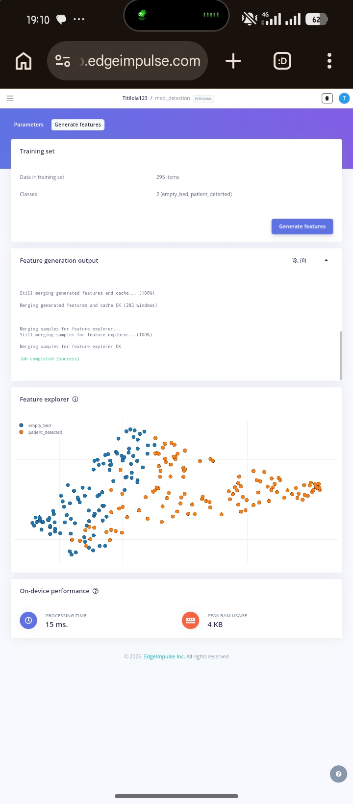 --- 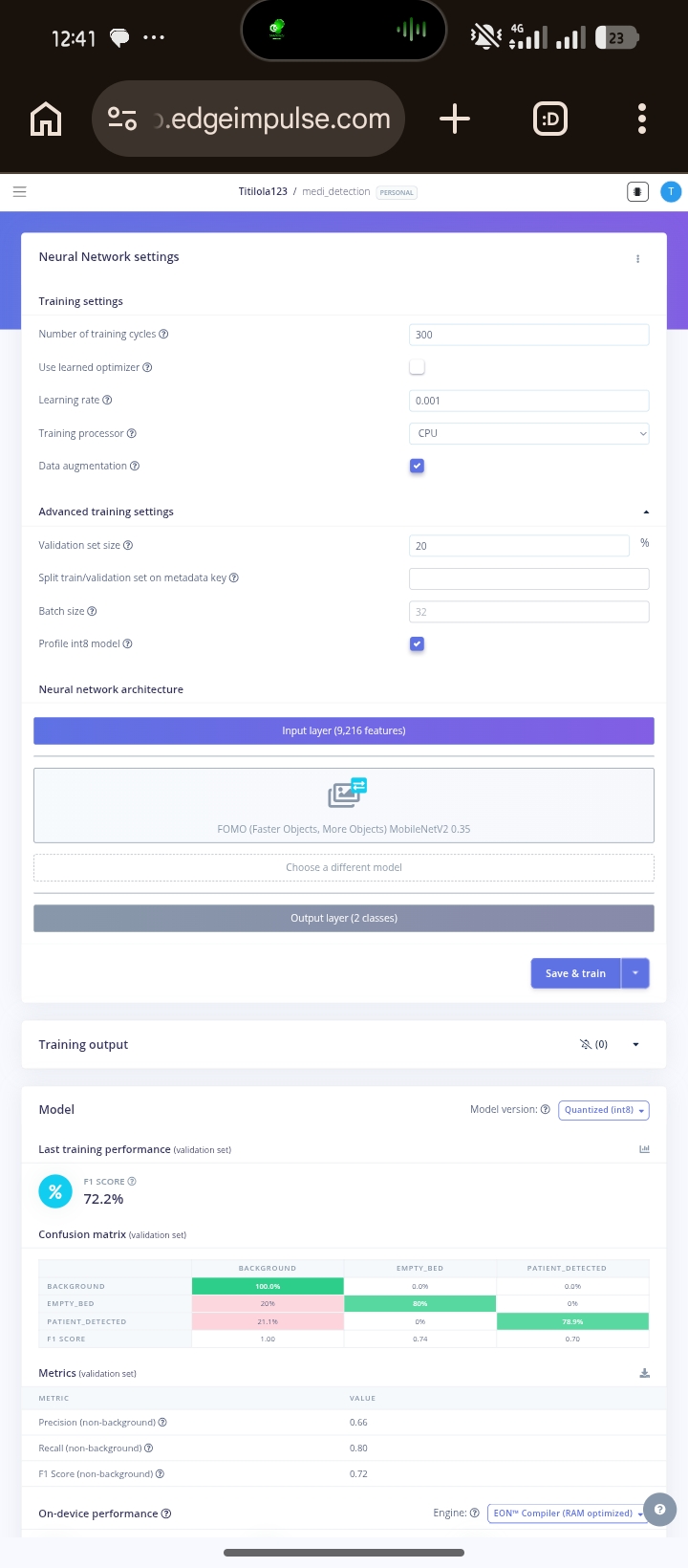 --- ## The Technology Behind It MediBot is built entirely on open tools and affordable hardware. ### Hardware - ESP32 Dev Module - ESP32-CAM - MAX30102 pulse oximeter - MLX90614 infrared temperature sensor - Active buzzer - WiFi communication ### AI and Machine Learning - TensorFlow Lite - Edge Impulse - face-api.js - MobileNetV1 - TinyFaceDetector - FOMO object detection ### Backend - Supabase - PostgreSQL - Real-time subscriptions - Role-based access control ### Frontend - Vanilla JavaScript - HTML - CSS - Progressive Web App deployment --- ## What Makes This Important MediBot is not important because it uses artificial intelligence. It is important because it demonstrates that useful healthcare technology can be built locally around Nigerian realities instead of imported assumptions. The system shows that: - Contactless patient monitoring can be affordable - Embedded AI can run on low-cost hardware - Real-time monitoring does not require expensive infrastructure - Local engineering can solve local healthcare problems The monitoring gap in Nigerian hospitals is not only a funding problem. It is also an engineering problem. MediBot was built as an engineering response to that gap. --- ## Current Development Status | Component | Status | |-----------|--------| | ESP32 vitals firmware | Complete | | Supabase data pipeline | Complete | | Dashboard | Complete | | Phone camera AI monitoring | Complete | | Login system | Complete | | Real-time alert system | Complete | | ESP32-CAM integration | In progress | | Bed occupancy model | In training | | Expression classifier | Dataset collection ongoing | | Offline local mode | Planned | | Clinical validation | Planned | --- ## What Comes Next The immediate roadmap is completing the ESP32-CAM vision pipeline, improving embedded AI models, and beginning clinical validation in real patient environments. Long term, the goal is broader deployment in Nigerian hospitals and further development of locally built robotics and embedded AI systems for healthcare. The talent to build these systems already exists here. What has been missing is infrastructure, research continuity, and systems designed specifically for the realities we actually operate in. MediBot is part of building that foundation. --- > The monitoring gap in Nigerian hospitals cannot be solved by importing more expensive equipment alone. It requires systems designed specifically for the environments where the need is real. MediBot was built around that reality from the beginning.
Smart IOT Security Box
```javascript // Simulating the Security Box Heartbeat Monitor const deviceId = "DEVICE_001"; let logs = []; function simulateHeartbeat() { const timestamp = new Date().toLocaleTimeString(); const status = Math.random() > 0.1 ? "✅ ONLINE" : "⚠️ WARNING (Latency)"; const entry = `[${timestamp}] ${deviceId}: ${status}`; logs.unshift(entry); // Add to the top // Keep only last 5 logs if (logs.length > 5) logs.pop(); console.clear(); console.log("=== SMART SECURITY BOX LIVE MONITOR ==="); logs.forEach(log => console.log(log)); console.log("\nNext check in 3 seconds..."); } // Start the simulation setInterval(simulateHeartbeat, 3000); simulateHeartbeat(); ```
 Web App
85
Web App
85
Lliuq: A Serverless AI Platform for Accessible Scholarship and Academic Preparation
# Lliuq: A Serverless AI Platform for Accessible Scholarship and Academic Preparation ## What I Built Lliuq is a browser-based suite of AI-powered productivity tools built for one purpose: helping people put their best work forward when it matters most, without a paywall in the way. I was preparing for a scholarship interview when I hit the third paywall in one night. Every tool that could actually help had a gate in front of it. The help existed. The technology was always there. But what did not exist was access. So I built this and made it free, because the distance between a prepared candidate and an unprepared one should never come down to what they can afford. That gap is not a minor inconvenience. It is the mechanism through which opportunity reproduces itself in the hands of people who already have it. Lliuq is a direct technical response to that mechanism. Every architectural decision, from the serverless infrastructure to the zero-cost model to the privacy-first data handling, was made with one constraint in mind: the student in Lagos or Accra or Nairobi preparing for a scholarship interview at midnight should have access to the same quality of preparation tools as anyone else, anywhere in the world. That is SDG 4 and SDG 10, not as stated goals but as design requirements written into the first line of code. The platform currently has three live AI tools with a fourth under development: 1. **Scribe** records audio and produces structured, formatted documents using Whisper and Llama. Not raw text but proper meeting minutes, lecture notes, sermon summaries, and song transcriptions, each with auto-generated metadata including tone classification, estimated reading time, and transcription confidence scoring, so that no key point is lost, action items are clearly noted, and the people in the room can be present in the conversation instead of racing to write it down 2. **Interview** is a scholarship interview simulator. It generates contextual questions across ten distinct categories, scores spoken answers on content depth and grammar, detects filler words in real-time, measures words per minute, and returns model answers alongside three concrete improvement tips. The entire evaluation is returned as structured JSON from Llama and parsed directly in the browser, allowing candidates to identify exactly where they lost points, what they said that weakened their answer, and what a stronger response would have sounded like. 3. **Prose** is a statement of purpose builder with pre-listed support for over 100 universities worldwide, including institutions across Africa, Europe, Asia, and North America, and for any university or scholarship not on the list, the user can type it in manually. It uses Llama to generate and refine application writing tailored to the specific university and programme the user is applying to, because writing with clarity in your first language and writing the kind of statement of purpose that Cambridge or Harvard expects are two entirely different skills, and the gap between them should not be the reason an application fails. Everything runs entirely in the browser. No account needed. Nothing is stored on any server. The user connects their own free Groq API key, and the platform is ready to use. The platform never touches your key. ## Code Examples The platform has no backend. Every AI call goes directly from the browser to Groq over HTTPS. ```javascript const response = await fetch("https://api.groq.com/openai/v1/chat/completions", { method: "POST", headers: { "Authorization": `Bearer ${apiKey}`, "Content-Type": "application/json" }, body: JSON.stringify({ model: "llama-3.3-70b-versatile", messages: conversationHistory, response_format: { type: "json_object" } }) }); ``` For the Interview module, audio is captured via the browser MediaRecorder API and sent to Groq's Whisper endpoint for transcription before evaluation: ```javascript const mime = MediaRecorder.isTypeSupported("audio/webm;codecs=opus") ? "audio/webm;codecs=opus" : "audio/webm"; const recorder = new MediaRecorder(stream, { mimeType: mime }); recorder.onstop = async () => { const blob = new Blob(allChunks, { type: mime }); const fd = new FormData(); fd.append("file", blob, "audio.webm"); fd.append("model", "whisper-large-v3"); const res = await fetch("https://api.groq.com/openai/v1/audio/transcriptions", { method: "POST", headers: { "Authorization": `Bearer ${apiKey}` }, body: fd }); }; ``` The Interview engine enforces non-repetitive questioning through a structured system prompt. Llama tracks which of the ten question categories it has already used and is forbidden from repeating one within a session: ```javascript const SYSTEM_PROMPT = ` QUESTION VARIETY RULES: Categories: [opening/motivation, academic achievement, leadership, community/social impact, adversity/resilience, future vision, values/ethics, scholarship fit, critical thinking, personal character] Each question MUST come from a DIFFERENT category than the previous one. Never ask two questions from the same category in one session. Make questions specific to the scholarship name, university, and the field of study provided. `; ``` Scribe uses a switchable system prompt architecture. The format type the user selects determines which AI persona and output structure loads. A meeting prompt loads a professional secretary persona that produces structured minutes. A lecture prompt loads a Prodigy student persona that generates hierarchical notes with cross-disciplinary connections. The same raw audio produces structurally different documents depending entirely on which system prompt is active. # Result 1. Lliuq is live at [lliuq.netlify.app](https://lliuq.netlify.app) with no account required. Three functioning tools are now available. 2. The platform proves that a useful, privacy-respecting AI product does not always need a backend, a subscription model, or a company behind it. By routing all inference through the user's own Groq API key and persisting state entirely in localStorage, Lliuq eliminates infrastructure costs at the platform level and passes that zero cost directly to the user. This is what responsible AI for Good looks like when the architecture itself is the commitment. 3. The Interview module delivers five-question sessions with real-time speech scoring across content depth, grammar accuracy, confidence, calmness, and vocal pace, all evaluated by Llama and returned as structured JSON. The Scribe engine produces formatted documents from raw audio using Whisper for transcription and Llama for restructuring. The Prose module generates university-specific application writing using contextual prompts built around the institution and programme the applicant is targeting. 4. Users supplying their API key allow them access to all the tools. The API Key itself comes with a generous allocation of free tokens. The community this platform is built for is the student who cannot afford a coaching session, the applicant who found every free tool behind a trial limit, and the candidate who is every bit as qualified as anyone else in the room but has less time and less money to prepare. 5. Since there is no server, account, or database, the user data stays secured on their local browser storage, and clearing it removes everything. ## Conclusion The goal was never to build another AI wrapper. It was to make the kind of preparation that changes outcomes available to anyone who needs it, regardless of what they can pay. And it delivers.
No projects match
Try a different search or filter