About the project
# Fire Suppression Robot
## Project Overview
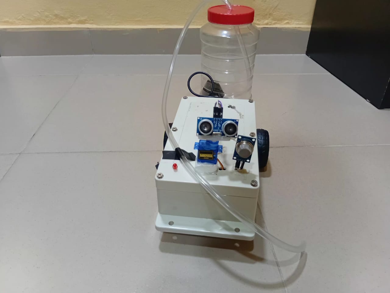
The Fire Suppression Robot is an autonomous firefighting system designed to detect and suppress fires in their early stages. Built on the ESP8266 microcontroller platform, this robot combines smoke detection capabilities with a mobile water-based suppression system to provide rapid response to fire emergencies.
The system continuously monitors its environment using a smoke detector sensor and also receives signals from fixed sensors . Upon detecting smoke or fire, it automatically activates a water pump to suppress the flames while simultaneously sending real-time alerts via WiFi to notify users of the emergency.I used the Blynk app for the Alerts The robot's custom-built chassis houses DC motors that enable mobility, allowing it to navigate toward fire sources or patrol designated areas.
This project demonstrates the integration of IoT technology with robotics to create an affordable, responsive fire safety solution suitable for homes, small offices, and educational environments.
## Table of Contents
- [Project Overview](#project-overview)
- [Features](#features)
- [Tech Stack](#tech-stack)
- [Hardware Components](#hardware-components)
- [System Architecture](#system-architecture)
- [Installation & Setup](#installation--setup)
- [Usage](#usage)
- [Future Improvements](#future-improvements)
## Features
- Autonomous smoke detection
- WiFi-enabled remote monitoring
- Automated water-based fire suppression
- Real-time alerts
## Tech Stack
**Hardware:**
- ESP8266 WiFi Microcontroller
- Smoke Detector Sensor
- DC Motors (for mobility)
- Water Pump (fire suppression mechanism)
- Lithium Battery (power supply)
- Custom-built chassis
**Software:**
- C++ (Arduino framework)
- WiFi connectivity for remote monitoring/control
**Communication:**
- WiFi Protocol (ESP8266 built-in)
## Hardware Components
| Component | Specification | Purpose |
|-----------|--------------|---------|
| ESP8266 | NodeMCU | Main microcontroller |
| Smoke Sensor | MQ-2/MQ-135 | Smoke detection |
| Ultrasonic Sensor | HC-SR04 | Obstacle detection/distance measurement |
| DC Motors | 6V/12V | Robot mobility |
| Servo Motor | SG90/MG995 | Directional control/pump positioning |
| Water Pump | 3-6V | Fire suppression |
| LED | 5mm/RGB | Status indicator/alerts |
| Battery | Li-ion 3.7V | Power supply |
| Motor Driver | L298N/L293D | DC motor control |
| Relay Module | 5V | Water pump control |
## System Architecture
[Smoke Sensor] --> [ESP8266] --> [Motor Driver] --> [DC Motors]
|
+--> [Water Pump]
|
+--> [WiFi Module] --> [Remote Monitor]
## Installation & Setup
### Prerequisites
- Arduino IDE
- ESP8266 Board Package
- Blynk IoT account and mobile app
- Required libraries:
```cpp
#include <ESP8266WiFi.h>
#include <BlynkSimpleEsp8266.h>
```
### Steps
#### 1. Blynk IoT Setup
1. Download and install the **Blynk IoT app** (iOS/Android)
2. Create a new account or login
3. Create a new project and select **ESP8266** as device
4. Copy the **Auth Token** sent to your email
5. Configure datastreams/widgets for:
- Smoke level indicator
- Fire alert notifications
- Pump status
- System status display
#### 2. Arduino IDE Setup
1. Clone or download the project
2. Open the `.ino` file in Arduino IDE
3. Install required libraries via Library Manager:
- ESP8266WiFi
- Blynk (by Volodymyr Shymanskyy)
4. Update credentials in the code:
```cpp
#define BLYNK_AUTH_TOKEN "YourAuthToken"
const char* ssid = "YOUR_SSID";
const char* password = "YOUR_PASSWORD";
```
5. Select **ESP8266 board** from Tools > Board
6. Select correct **COM port**
7. Upload the code to ESP8266
#### 3. Hardware Assembly
1. Connect smoke sensor to ESP8266 analog pin
2. Connect DC motors to motor driver
3. Connect water pump to relay module
4. Wire motor driver and relay to ESP8266 GPIO pins
5. Connect lithium battery with proper voltage regulation
6. Test all connections before powering on
### Wiring Diagram
## Code Structure
```cpp
#define BLYNK_PRINT Serial
#define BLYNK_TEMPLATE_ID "TMPL2r2DgC4O2"
#define BLYNK_TEMPLATE_NAME "SMART SMOKE DETECTOR"
#define BLYNK_AUTH_TOKEN "Ngaw17Ft_n5gy_7ul5KI-jvk7r7cFNNU"
#include <ESP8266WiFi.h>
#include <BlynkSimpleEsp8266.h>
#include <Servo.h>
char ssid[] = "Galaxy A06 361f";
char pass[] = "SharonvAzeezat";
const int IN1 = D1;
const int IN2 = D2;
const int IN3 = D3;
const int IN4 = D4;
const int LED_PIN = D8;
const int RELAY_PIN = D7;
const int MQ2_PIN = A0;
const int TRIG_PIN = D5;
const int ECHO_PIN = D6;
const int SERVO_PIN = D0;
Servo myServo;
const int SMOKE_THRESHOLD = 450;
bool fireDetected = false;
unsigned long lastAlertTime = 0;
const unsigned long ALERT_COOLDOWN = 10000;
void stopRobot() {
digitalWrite(IN1,LOW);
digitalWrite(IN2,LOW);
digitalWrite(IN3,LOW);
digitalWrite(IN4,LOW);
}
void moveForward() {
digitalWrite(IN1,LOW);
digitalWrite(IN2,HIGH);
digitalWrite(IN3,LOW);
digitalWrite(IN4,HIGH);
}
void moveBackward() {
digitalWrite(IN1,HIGH);
digitalWrite(IN2,LOW);
digitalWrite(IN3,HIGH);
digitalWrite(IN4,LOW);
}
void turnLeft() {
digitalWrite(IN1,HIGH);
digitalWrite(IN2,LOW);
digitalWrite(IN3,LOW);
digitalWrite(IN4,HIGH);
}
void turnRight() {
digitalWrite(IN1,LOW);
digitalWrite(IN2,HIGH);
digitalWrite(IN3,HIGH);
digitalWrite(IN4,LOW);
}
long getDistance() {
digitalWrite(TRIG_PIN, LOW);
delayMicroseconds(2);
digitalWrite(TRIG_PIN, HIGH);
delayMicroseconds(10);
digitalWrite(TRIG_PIN, LOW);
long duration = pulseIn(ECHO_PIN, HIGH, 30000);
if (duration == 0) return 999;
return duration * 0.034 / 2;
}
long scanDistance(int angle) {
myServo.write(angle);
delay(400);
return getDistance();
}
void setup() {
Serial.begin(115200);
pinMode(RELAY_PIN, OUTPUT);
pinMode(LED_PIN, OUTPUT);
pinMode(IN1, OUTPUT); pinMode(IN2, OUTPUT);
pinMode(IN3, OUTPUT); pinMode(IN4, OUTPUT);
pinMode(TRIG_PIN, OUTPUT);
pinMode(ECHO_PIN, INPUT);
myServo.attach(SERVO_PIN);
myServo.write(90);
stopRobot();
Serial.println("Warming up MQ2 sensor...");
delay(3000);
Blynk.begin(BLYNK_AUTH_TOKEN, ssid, pass);
}
void loop() {
Blynk.run();
int smokeLevel = analogRead(MQ2_PIN);
long distance = getDistance();
Blynk.virtualWrite(V3, smokeLevel);
Blynk.virtualWrite(V9, distance);
Serial.print("Smoke: "); Serial.print(smokeLevel);
Serial.print(" | Distance: "); Serial.println(distance);
if (smokeLevel > SMOKE_THRESHOLD) {
fireDetected = true;
stopRobot();
digitalWrite(RELAY_PIN, HIGH);
digitalWrite(LED_PIN, HIGH);
if (millis() - lastAlertTime > ALERT_COOLDOWN) {
Blynk.logEvent("fire_alert", "CRITICAL: Smoke detected!");
lastAlertTime = millis();
}
return;
}
fireDetected = false;
digitalWrite(RELAY_PIN, LOW);
digitalWrite(LED_PIN, LOW);
if (distance > 0 && distance < 25) {
stopRobot();
delay(200);
long leftDist = scanDistance(150);
long rightDist = scanDistance(30);
myServo.write(90);
delay(300);
if (leftDist > rightDist) {
turnLeft();
} else {
turnRight();
}
delay(500);
stopRobot();
} else {
moveForward();
}
}
```
## Future Improvements
- [ ] Add camera for visual fire detection
- [ ] Multiple fire suppression mechanisms
- [ ] Mobile app integration
## Challenges Faced
### 1. Power Supply and Battery Configuration
**Challenge:** Difficulty in selecting appropriate power supply and battery configuration for the diverse power requirements of different components.
**Solution:** Conducted thorough analysis of each component's voltage and current requirements. Implemented a lithium-ion battery with appropriate voltage regulation to ensure stable power delivery across all subsystems.
---
### 2. Power Distribution and Safety
**Challenge:** Challenges in distributing power across multiple components (ESP8266, motors, pump, sensors, servo) safely without causing damage or electrical hazards.
**Solution:** Used separate power rails with appropriate current limiting and protection circuits. Implemented bypass capacitors to stabilize voltage and prevent voltage spikes from affecting sensitive components.
---
### 3. High-Current Pump Integration
**Challenge:** Issues integrating a high-current water pump with low-power control circuitry without damaging the ESP8266.
**Solution:** Utilized a relay module to isolate the high-current pump circuit from the ESP8266's control pins. This allowed safe switching of the pump while protecting the microcontroller from current surges.
---
### 4. System Integration
**Challenge:** Difficulty combining multiple subsystems (smoke detection, motor control, water suppression, WiFi communication, obstacle detection) into a single cohesive working system.
**Solution:** Developed modular code structure with separate functions for each subsystem. Implemented non-blocking code practices and careful timing management to ensure all systems operated harmoniously without interference
---
 Oyinlade Precious OtunlaRAIN trainee

 RAIN
RAIN